

News

Miro: A New Standard in Responsible Innovation

Miro: A New Standard in Responsible Innovation The Miro monitor arm is setting new benchmarks in sustainability. It offers a high-performance solution without compromising on environmental responsibility. Designed with careful material selection, local sourcing, and longevity in mind, Miro’s responsible approach to design and unique manoeuvrability set it apart from the competition. Sustainable Choices Miro is crafted from energy-efficient materials with a lower carbon impact....

Read more
HSE Advisor

Role Purpose Support in the development, implementation and maintenance of the company’s Health, Safety & Environmental policies, processes, operational procedures, and standards.  Ensuring best practice and championing a continually improving HSE culture within the business. Key Responsibilities Liaise with and provide support to all areas of the business to eliminate, mitigate or reduce identified HSE exposures. Partner with the production management team and team leaders,...

Read more
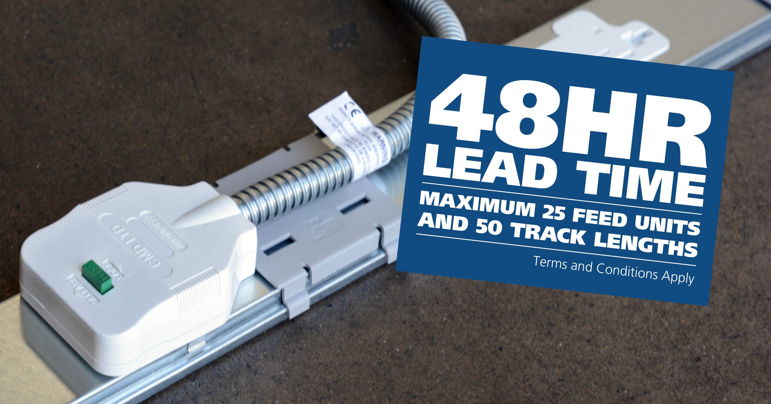
CMD Ltd LAUNCHES 48-HOUR TURNAROUND ON BETATRAK® RAPID ORDERING SERVICE

CMD Ltd, the specialist in power distribution systems, workstation power and monitor arms, has launched a rapid ordering service for its Betatrak® underfloor powertrack distribution systems and accessories, with a commitment to delivering within 48-hours of an approved purchase order*. The service enables customers to order up to 50 lengths of Standard or Clean Earth (C/E) low noise Betatrak, along with up to 25 feed...

Read more
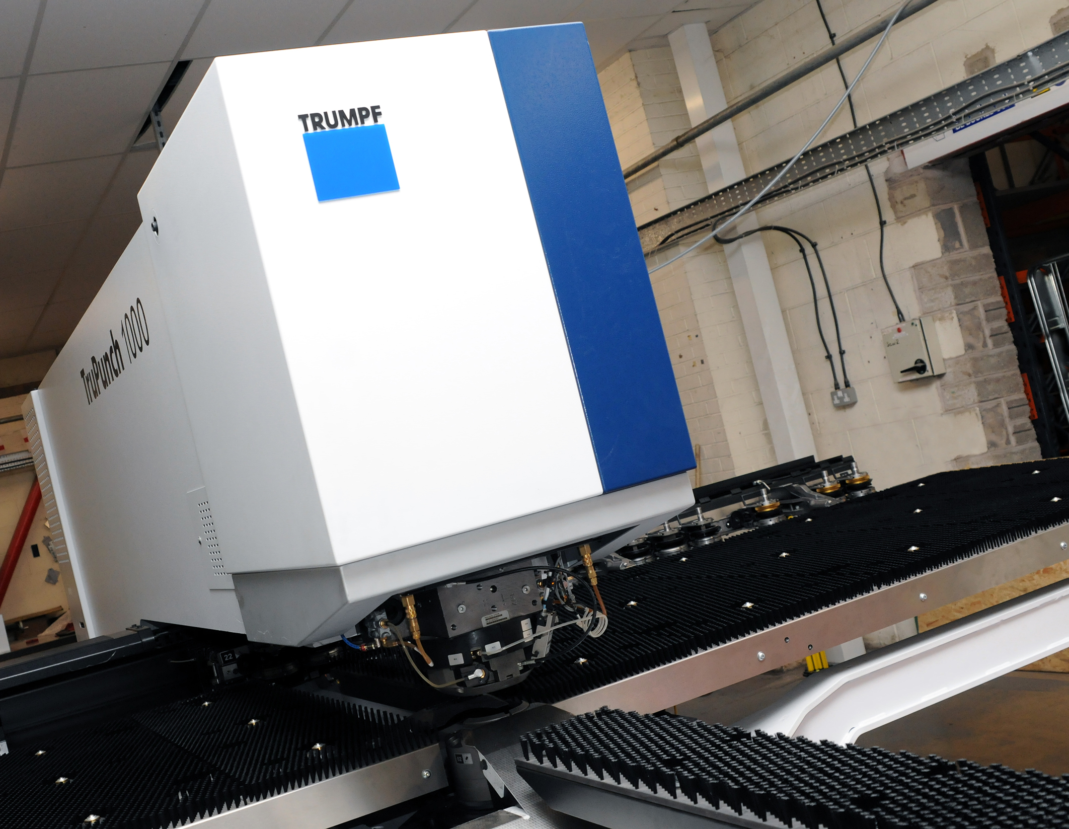
CMD INVESTS £1/4 MILLION IN NEW MACHINE AS PART OF FACTORY UPGRADE

We have invested in a new £1/4m TRUMPF CNC metal punch as part of an asset renewal strategy for our UK manufacturing capability. The new machine will be used in the production of a wide variety of our power distribution systems and workstation power products at our Rotherham factory. Suitable for handling sheet metal between 0.9mm and 3.0mm thick, the new machine will replace one...

Read more
CMD CATALOGUE PROVIDES TECHNICAL POWER DISTRIBUTION GUIDE

CMD Ltd has released a new catalogue, providing an easy to follow technical guide to our power distribution systems and plug and play desk modules. Detailing CMD’s full range of UK-manufactured power distribution systems and plug and play desk modules, the catalogue will be a helpful source of information to M&E engineers and contractors alike to understand how our power distribution systems connect together and...

Read more
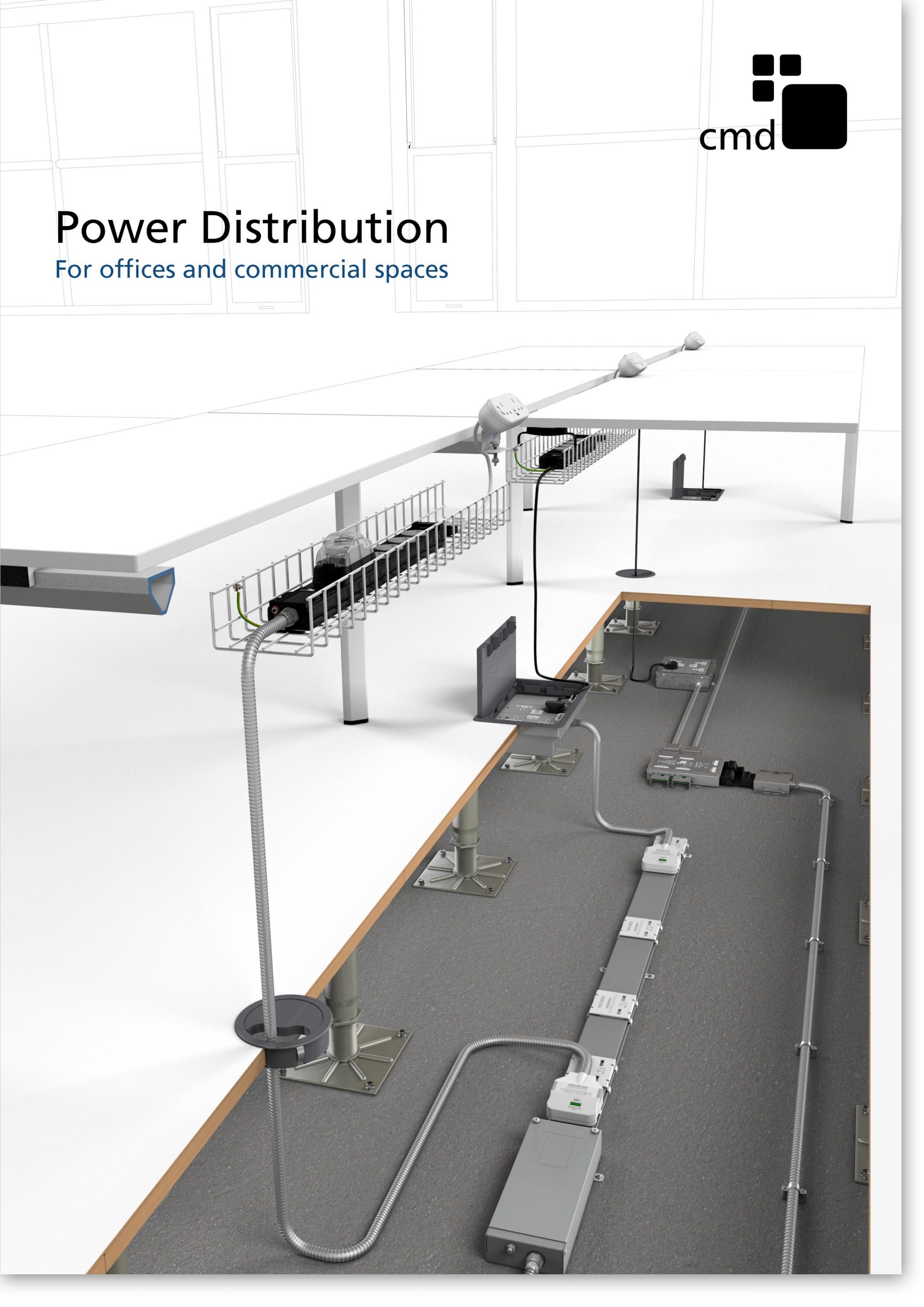
Power Distribution Catalogue
CMD Ltd PLAYS ESSENTIAL ROLE IN ELECTRICAL FIT OUT AT LONDON’S PRESTIGIOUS OFFICE DEVELOPMENT

CMD Ltd, specialist in workplace connectivity and ergonomic solutions, has provided a flexible and high-quality power distribution network for The Ray, a prestigious office development in London’s Farringdon. Well-known for being the former site of The Guardian newspaper, The Ray now stands as an 83,000ft² office development characterised by a modernised warehouse aesthetic, with level two now occupied by a global social media company. The...

Read more

The Ray
CMD plugs in to european opportunity with Schuko Capsule unit launch

CMD Ltd, the specialist in power and connectivity solutions for commercial environments, has launched a Schuko version of its popular fixed format Capsule workstation power module for export to mainland Europe and beyond. A popular on desk power module comprising two sockets and dual USB (type A and C) chargers, CMD’s Capsule unit is already widely specified in the UK as an off-the-shelf workstation power...

Read more
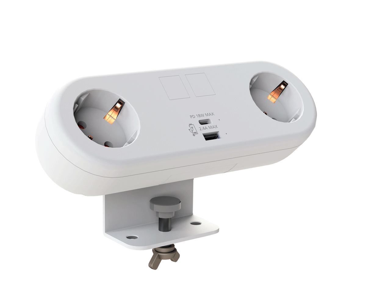
CMD White Schuko Capsule Desk Power Module
CMD LTD EXTENDS MONITOR ARM RANGE WITH THE LAUNCH OF REACH PLUS

CMD Ltd, the specialist in ergonomic and connectivity solutions for commercial interiors, has completed its Reach monitor arm range with the launch of the Reach Plus. Available in single or dual screen options, the Reach Plus has been designed to provide an ideal solution for both single and dual screen workstation configurations, or can be used with next generation of large format curved screens. Suitable...

Read more

CMD Ltd DEMONSTRATES THE ART OF POWER DISTRIBUTION AT THE UNIVERSITY OF WARWICK

CMD Ltd, the specialist in workplace connectivity and ergonomic solutions, has provided Betatrak busbar power distribution and a range of electrical accessories for two major capital investment projects at the University of Warwick. Designed by Fielden Clegg Bradley Studios, the £33 million Faculty of Arts building is a showpiece development comprising four interconnected structures set around a central atrium, which will enable inter-disciplinary collaboration across...

Read more

University of Warwick
CMD BRINGS HARMONY TO COVENTRY UNIVERSITY RESEARCH FACILITIES

CMD Ltd, the specialist in power distribution solutions and workstation power and ergonomics, has provided under desk and on desk power modules for the refurbishment of three Coventry University research buildings. Located on Coventry University Technology Park, a business park designed to encourage collaboration between the university and knowledge-based businesses, the three buildings are being repurposed as office accommodation for university research teams. The refurbishment...

Read more

Coventry University

What Are the Top Types of Electrical Relays?

Choosing a relay begins with a practical question: what must it control, and under what conditions? Electromechanical relays use moving contacts, while solid-state relays switch electronically. Thermal overload relays help protect motors from sustained overcurrent. Time-delay, latching, reed, and safety relays each serve more specific roles. The categories overlap more than a tidy chart suggests. That can make selection less simple than it looks.

J. Lewis Blackburn, coauthor of Protective Relaying: Principles and Applications, is a recognized authority in the field. A practical paraphrase of the selective-protection principle reflected in his work is: “Detect the fault, then isolate only the affected circuit.” This is a paraphrase, not a direct quotation. It captures why relay choice matters: a relay must match the circuit, load, and operating conditions. A small control-panel relay may not suit frequent switching or a harsh environment. Check contact ratings, coil voltage, switching frequency, and installation conditions against the manufacturer’s specifications. Relays Electrical professionals also consider what happens when power fails or a contact wears. Details matter. This guide compares the top types of electrical relays, explains their common uses, and notes where each type may fall short. Some choices still need careful review. A relay’s label alone cannot tell the whole story.

What Are the Top Types of Electrical Relays?

Electromechanical Relays: Mechanical Life Often Reaches 10⁷ Operations

Electromechanical relays use a coil and moving contacts to switch a circuit. Their mechanical life often reaches 10⁷ operations, or ten million cycles, under specified test conditions. That figure generally describes movement without a significant electrical load. It is not a promise of ten million successful switches in every installation. IEC 61810-1:2015 sets out testing and measurement methods for electromechanical elementary relays, helping engineers compare stated performance more consistently.

Still, the number can mislead. Contact wear depends on switched voltage, current, load type, and how often the relay operates. An inductive load, such as a small motor, can create an arc when contacts open. That arc may erode contact surfaces long before the mechanism reaches its mechanical endurance limit. A relay tested at no load may therefore outlast one switching a real circuit by a wide margin.

In practical selection, compare mechanical endurance with electrical endurance at the intended load, not as interchangeable figures. Check the test voltage, current, switching frequency, and failure criteria in the technical documentation. A relay clicking on a quiet bench sounds reassuring. But sound alone is poor evidence of remaining life. Inspect operating conditions, and leave room for uncertainty; real panels rarely behave exactly like laboratory setups.

Solid-State Relays: AC On-State Voltage Drops Commonly Measure 1–2 V

Solid-state relays switch AC loads without moving contacts, so they avoid mechanical contact wear. Their output devices still dissipate heat. Published AC solid-state relay specifications commonly show an on-state voltage drop of about 1–2 V; IEC 62314:2006 identifies this as a key performance characteristic. At 5 A, a 1.5 V drop means roughly 7.5 W of heat inside the relay. That is enough to warm a small control cabinet.

Check the voltage-drop figure at your actual load current, not just the headline rating. A resistive heater may behave predictably, while a motor or transformer can bring higher inrush current. The relay’s temperature, mounting surface, and heatsink also affect its safe operating current. That rule is useful, but not the whole story: published figures often reflect specific test conditions. Small detail, big difference.

Tips: At 5 A, allow for about 5–10 W of relay heat when estimating a 1–2 V drop. Verify the datasheet’s test conditions, then check the case temperature under real load. A quick bench test can reveal what the calculation misses.

Reed Relays: Typical Operate Times Can Be Below 1 ms

Reed Relays: Typical Operate Times Can Be Below 1 ms

Reed relays can switch quickly because a magnetic field moves two thin contacts sealed inside a glass capsule. In many designs, operate time can fall below one millisecond. That makes them useful when a test instrument must change signal paths promptly, or when a control circuit needs crisp, repeatable switching. The glass enclosure also helps protect the contacts from dust and oxidation. Small details matter.

That figure is not a complete measure of switching performance. Operate time usually describes the interval from coil energization to contact closure, but the exact definition can vary by specification. Release time, contact bounce, and external circuit conditions also affect when a signal becomes stable. A relay may close in under one millisecond and still produce brief bouncing afterward. Check the timing diagram.

In practical use, coil voltage, drive circuitry, load type, and temperature can shift the observed result. A low-level signal and an inductive load do not stress contacts in the same way. Measure the relay in the intended circuit, using an oscilloscope or suitable timing equipment, rather than relying on a headline number alone. I would also leave margin in timing-sensitive designs; specifications are helpful, but real setups can be less tidy than the bench.

What Are the Top Types of Electrical Relays? - Reed Relays: Typical Operate Times Can Be Below 1 ms
Relay Type How It Works Typical Operate Time Main Advantages Common Uses and Considerations
Reed relay A coil’s magnetic field moves sealed ferromagnetic reeds to open or close the contacts. Often below 1 ms; timing depends on the relay design and whether operate or release time is specified. Fast switching, low contact leakage, and a sealed contact environment. Used in test equipment, instrumentation, and signal switching. Contact ratings and switching life are limited compared with many power relays.
General-purpose electromechanical relay An energized coil moves an armature that mechanically operates electrical contacts. Commonly about 5–20 ms, excluding contact bounce and external circuit delays. Provides physical contact isolation and can switch a range of AC or DC loads. Used in control panels, appliances, and industrial control. Mechanical wear and contact arcing can limit service life.
Solid-state relay (SSR) Semiconductor devices switch the load without moving mechanical contacts. From under 1 ms to several milliseconds for many designs. AC zero-crossing types may wait until the next voltage zero crossing—up to about 8.3 ms at 60 Hz or 10 ms at 50 Hz. Silent operation, no mechanical contact wear, and suitability for frequent switching. Used in heaters, process control, and fast switching applications. SSRs can have off-state leakage and generate heat while conducting.
Latching relay A magnetic or mechanical latch holds the contact state after a brief set or reset signal. Typically several milliseconds to a few tens of milliseconds, depending on construction. Maintains its state without continuous coil power. Used in energy-saving control, meters, and memory-style switching. The control circuit must provide the correct set and reset pulses.
Automotive relay An electromagnetic coil moves contacts designed for vehicle electrical systems. Often around 5–20 ms; exact timing varies with the relay and operating conditions. Designed to switch vehicle loads and tolerate vibration when properly specified. Used for lamps, fans, pumps, and other vehicle circuits. Choose ratings appropriate to inrush current and the electrical environment.
Thermal overload relay A temperature-sensitive mechanism responds to sustained motor overcurrent and trips the control circuit. Usually seconds to minutes, depending on overload magnitude and trip class; it is not intended for fast signal switching. Provides time-delayed protection against sustained overloads. Used with motor starters. It is distinct from a short-circuit protective device and is selected to match the motor and application.

Timing values are typical ranges, not guaranteed specifications. Actual operate and release times depend on the relay design, load, coil drive, temperature, and the manufacturer’s test conditions.

Latching Relays: Bistable Designs Use Coil Power Only When Switching

Latching relays hold either an open or closed state after a brief switching pulse. Unlike a conventional relay, they do not need continuous coil power to maintain that state. Inside, a magnetic mechanism or mechanical latch keeps the contacts in position. That can reduce energy use and coil heating in equipment that stays switched on for long periods. The click may be brief, but the contact state remains.

A latching relay needs a new pulse to change state. Some designs use one coil with reversed-polarity pulses; others use separate set and reset coils. The control circuit must know the relay’s current state, since removing coil power does not automatically return contacts to their original position. This is easy to overlook. In practical installations, technicians may check the wiring diagram and test both switching directions before relying on the relay. A power interruption can also leave the system’s remembered state out of sync with the relay.

Tips: Match the coil pulse to the relay’s specified voltage and duration. Keep switching pulses distinct, and provide a way to confirm contact position when the application requires it. Latching relays can save power, but they are not automatically the best choice; control logic and reset behavior matter.

Thermal Overload Relays: IEC 60947-4-1 Defines Trip Classes 5–30

What Are the Top Types of Electrical Relays?

Thermal Overload Relays: IEC 60947-4-1 Defines Trip Classes 5–30

Thermal overload relays help protect motors from sustained overcurrent. Inside, a heater warms a bimetallic element, which bends and opens the control circuit. They do not replace short-circuit protection; that requires a coordinated protective device. Small details matter.

IEC 60947-4-1 defines trip classes by how quickly a relay trips at 7.2 times its current setting, starting from a cold state. Class 5 trips within 5 seconds; class 10A within 2–10 seconds; class 10 within 4–10 seconds. Classes 20 and 30 allow up to 20 and 30 seconds, respectively. These limits help match protection to a motor’s starting time and thermal capacity.

The U.S. Department of Energy’s 2014 report, Improving Motor and Drive System Performance: A Sourcebook for Industry, estimates that motor systems use about 68% of U.S. manufacturing electricity. That scale makes reliable motor protection important, but a trip class alone cannot determine the right relay. A heavily loaded pump and a fan may start differently, even with similar rated currents. Check the motor’s nameplate, expected starting duration, ambient temperature, and relay adjustment range. It is easy to overread the class number. Real installations can still need careful coordination.