

News

Miro: A New Standard in Responsible Innovation

Miro: A New Standard in Responsible Innovation The Miro monitor arm is setting new benchmarks in sustainability. It offers a high-performance solution without compromising on environmental responsibility. Designed with careful material selection, local sourcing, and longevity in mind, Miro’s responsible approach to design and unique manoeuvrability set it apart from the competition. Sustainable Choices Miro is crafted from energy-efficient materials with a lower carbon impact....

Read more
HSE Advisor

Role Purpose Support in the development, implementation and maintenance of the company’s Health, Safety & Environmental policies, processes, operational procedures, and standards.  Ensuring best practice and championing a continually improving HSE culture within the business. Key Responsibilities Liaise with and provide support to all areas of the business to eliminate, mitigate or reduce identified HSE exposures. Partner with the production management team and team leaders,...

Read more
CMD Ltd LAUNCHES 48-HOUR TURNAROUND ON BETATRAK® RAPID ORDERING SERVICE

CMD Ltd, the specialist in power distribution systems, workstation power and monitor arms, has launched a rapid ordering service for its Betatrak® underfloor powertrack distribution systems and accessories, with a commitment to delivering within 48-hours of an approved purchase order*. The service enables customers to order up to 50 lengths of Standard or Clean Earth (C/E) low noise Betatrak, along with up to 25 feed...

Read more

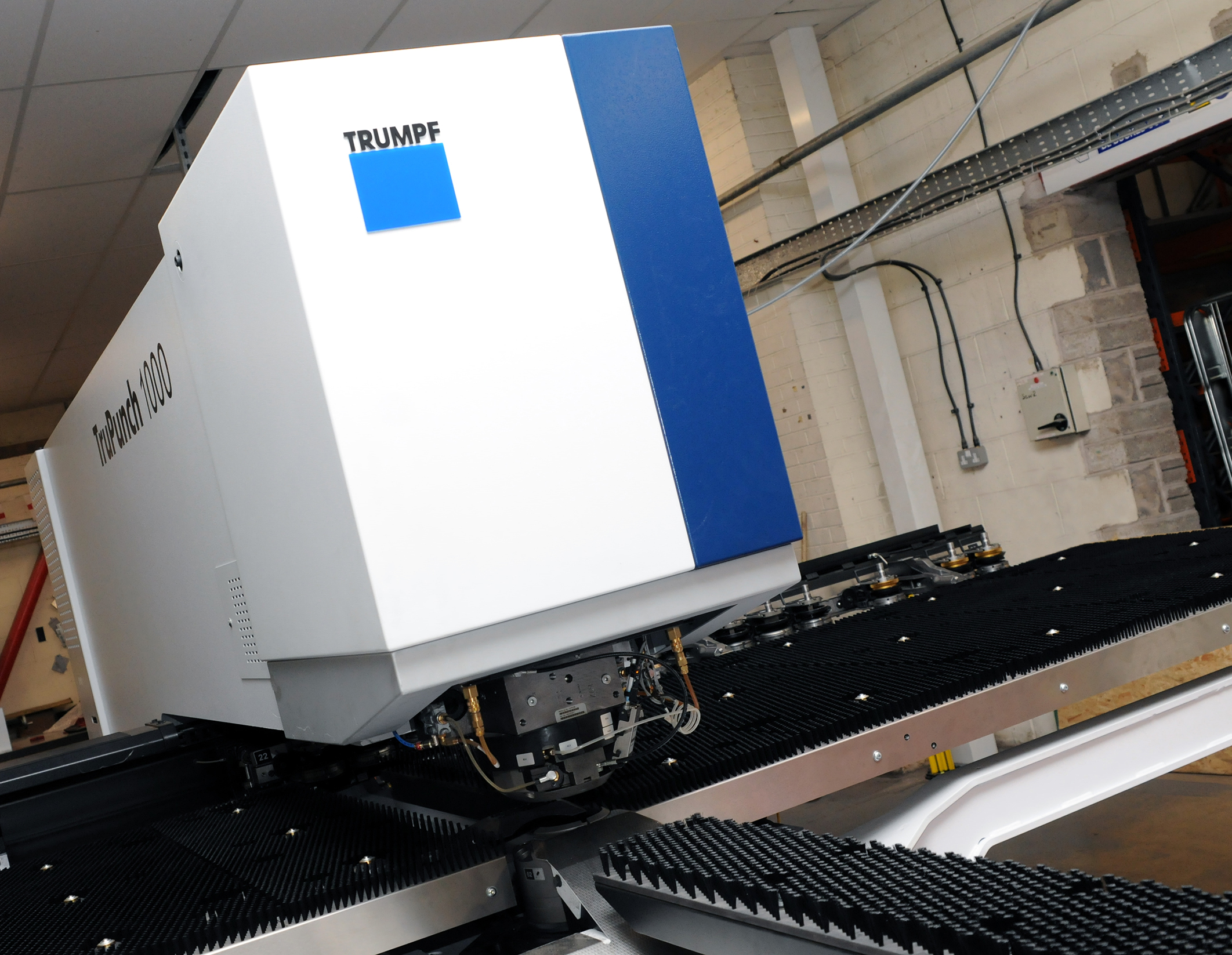
CMD INVESTS £1/4 MILLION IN NEW MACHINE AS PART OF FACTORY UPGRADE

We have invested in a new £1/4m TRUMPF CNC metal punch as part of an asset renewal strategy for our UK manufacturing capability. The new machine will be used in the production of a wide variety of our power distribution systems and workstation power products at our Rotherham factory. Suitable for handling sheet metal between 0.9mm and 3.0mm thick, the new machine will replace one...

Read more
CMD CATALOGUE PROVIDES TECHNICAL POWER DISTRIBUTION GUIDE

CMD Ltd has released a new catalogue, providing an easy to follow technical guide to our power distribution systems and plug and play desk modules. Detailing CMD’s full range of UK-manufactured power distribution systems and plug and play desk modules, the catalogue will be a helpful source of information to M&E engineers and contractors alike to understand how our power distribution systems connect together and...

Read more
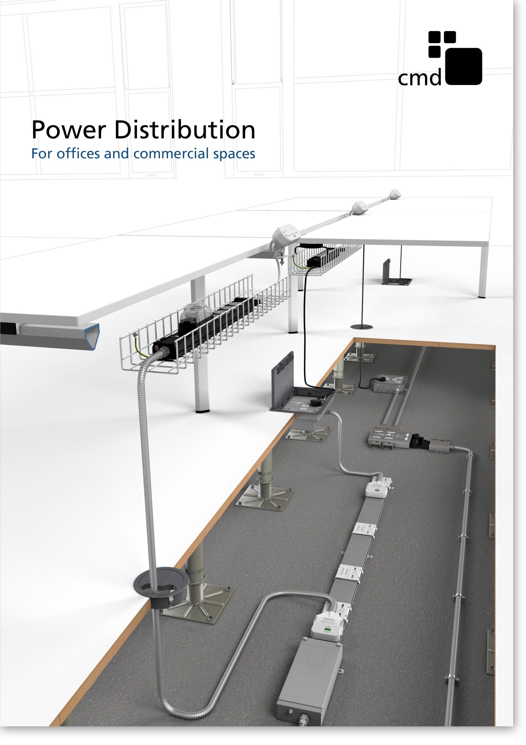
Power Distribution Catalogue
CMD Ltd PLAYS ESSENTIAL ROLE IN ELECTRICAL FIT OUT AT LONDON’S PRESTIGIOUS OFFICE DEVELOPMENT

CMD Ltd, specialist in workplace connectivity and ergonomic solutions, has provided a flexible and high-quality power distribution network for The Ray, a prestigious office development in London’s Farringdon. Well-known for being the former site of The Guardian newspaper, The Ray now stands as an 83,000ft² office development characterised by a modernised warehouse aesthetic, with level two now occupied by a global social media company. The...

Read more

The Ray
CMD plugs in to european opportunity with Schuko Capsule unit launch

CMD Ltd, the specialist in power and connectivity solutions for commercial environments, has launched a Schuko version of its popular fixed format Capsule workstation power module for export to mainland Europe and beyond. A popular on desk power module comprising two sockets and dual USB (type A and C) chargers, CMD’s Capsule unit is already widely specified in the UK as an off-the-shelf workstation power...

Read more
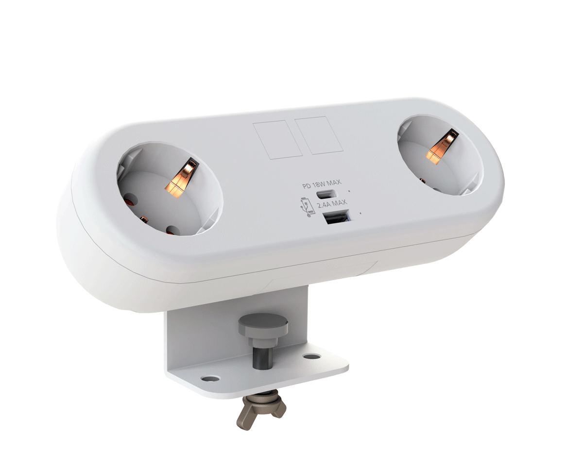
CMD White Schuko Capsule Desk Power Module
CMD LTD EXTENDS MONITOR ARM RANGE WITH THE LAUNCH OF REACH PLUS

CMD Ltd, the specialist in ergonomic and connectivity solutions for commercial interiors, has completed its Reach monitor arm range with the launch of the Reach Plus. Available in single or dual screen options, the Reach Plus has been designed to provide an ideal solution for both single and dual screen workstation configurations, or can be used with next generation of large format curved screens. Suitable...

Read more

CMD Ltd DEMONSTRATES THE ART OF POWER DISTRIBUTION AT THE UNIVERSITY OF WARWICK

CMD Ltd, the specialist in workplace connectivity and ergonomic solutions, has provided Betatrak busbar power distribution and a range of electrical accessories for two major capital investment projects at the University of Warwick. Designed by Fielden Clegg Bradley Studios, the £33 million Faculty of Arts building is a showpiece development comprising four interconnected structures set around a central atrium, which will enable inter-disciplinary collaboration across...

Read more

University of Warwick
CMD BRINGS HARMONY TO COVENTRY UNIVERSITY RESEARCH FACILITIES

CMD Ltd, the specialist in power distribution solutions and workstation power and ergonomics, has provided under desk and on desk power modules for the refurbishment of three Coventry University research buildings. Located on Coventry University Technology Park, a business park designed to encourage collaboration between the university and knowledge-based businesses, the three buildings are being repurposed as office accommodation for university research teams. The refurbishment...

Read more

Coventry University

What Is a Tapered Bearing and How Does It Work?

A Tapered Bearing is designed for loads that challenge ordinary bearings. It supports radial force, axial force, and combined loads in demanding machinery. Its inner and outer raceways form matching cone angles. The rollers sit between these surfaces, creating controlled rolling contact.

Picture a trailer wheel turning under weight. The bearing must carry the load while resisting side forces during a corner. Its geometry helps manage both forces through one compact assembly. The large and small ends of the rollers are guided by the cone-shaped raceways. This arrangement reduces sliding and helps maintain stable rotation.

As bearing researcher Dr. Tedric A. Harris wrote in Rolling Bearing Analysis, “A rolling bearing is a machine element that permits constrained relative motion.” That principle explains the Tapered Bearing clearly. It does not remove friction completely. It controls friction and transfers force more efficiently.

Small details matter. Incorrect preload can create heat, noise, and premature wear. Excessive clearance can allow movement, vibration, and uneven contact. Lubrication also changes performance. Too little lubricant damages surfaces. Too much may increase churning and temperature.

The design looks simple. It is not.

This guide will explain how a Tapered Bearing works, where its forces travel, and why adjustment matters. It will also examine common applications, material choices, lubrication, failure signs, and maintenance practices. Real performance depends on installation, alignment, load, speed, and operating conditions. A bearing can be technically correct yet still fail in service. That uncomfortable possibility deserves attention.

What Is a Tapered Bearing and How Does It Work?

Definition and Basic Structure of a Tapered Bearing

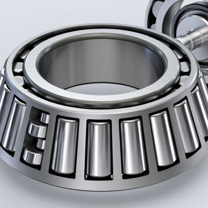
A tapered bearing is a rolling-element bearing designed to carry radial and axial loads at the same time. Its rollers are not straight cylinders; each roller narrows toward one end. The rollers sit between an inner ring, called the cone, and an outer ring, called the cup. These parts form a sloped running path. The cage keeps each roller spaced evenly.

Small details matter.

The bearing’s basic structure includes four working elements: the cone, cup, tapered rollers, and cage.

The cone has a raceway and a rib that guides the larger roller ends. The cup provides the matching outer raceway.

Because both raceways are angled, their contact lines meet at a common point on the bearing axis.

This geometry helps control thrust loads from gears, wheels, or rotating shafts. During inspection, I check roller spacing, raceway condition, and fit security. Uneven marks often reveal poor alignment or incorrect preload.

When the shaft turns, the rollers rotate and orbit between the two rings. Their tapered shape reduces sliding, although it does not remove friction.

Axial force pushes the rollers against the guiding rib, while radial force travels through the raceways.

Correct adjustment is essential. Excessive preload creates heat; too much clearance allows movement and noise.

A simple definition can mislead. Real performance also depends on lubrication, housing stiffness, installation accuracy, and temperature.

One overlooked washer can change the result.

Key Components and Their Functions

What Is a Tapered Bearing and How Does It Work?

Key Components and Their Functions

A tapered bearing uses conical rollers to support radial and axial loads at the same time. Its inner ring, often called the cone, carries the rollers and guides their movement. The outer ring, or cup, provides the matching raceway. Together, these raceways form a controlled rolling path. The rollers do the heavy work.

A cage spaces each roller evenly and prevents contact between neighboring rollers. This spacing helps distribute oil or grease across the contact surfaces. The cone’s ribs guide the rollers and resist thrust forces. Because the roller axes angle toward a common point, the bearing manages directional loads efficiently. Load direction matters.

During installation, technicians set clearance or preload carefully. Excessive preload creates heat, while loose adjustment allows vibration and uneven wear. A clean shaft shoulder, accurate seating, and suitable lubricant are essential. They influence whether the bearing runs smoothly at 1,500 rpm or develops damage quickly. In field inspections, dull raceway marks may suggest contamination or poor alignment, but diagnosis is not always obvious. Temperature, noise, mounting force, and lubricant condition should be checked together. The common mistake is blaming the bearing before checking the housing. Even experienced maintenance teams can miss that step.

How Tapered Bearings Handle Radial and Axial Loads

A tapered bearing uses angled rollers between an inner cone and an outer cup. This geometry lets it manage radial and axial loads at the same time. Radial load pushes toward the shaft center. Axial load acts along the shaft. The roller angle transfers both forces through the bearing raceways.

When a radial load enters the bearing, the rollers spread pressure along their contact lines. The tapered shape also creates an axial reaction. A greater contact angle usually improves axial capacity, but it can increase friction and heat. Two opposing bearings often control shaft movement in both directions. Correct adjustment matters. Excessive preload causes heat, while too much clearance allows vibration and uneven wear. Real assemblies rarely behave perfectly.

Tips: Check the load direction before selecting the bearing arrangement. Keep the shaft and housing aligned. Use clean lubricant and inspect the raceways for scoring, pitting, or discoloration. Measure operating temperature after installation. A small temperature rise may be normal, but a sudden increase needs attention. Do not assume the rated load guarantees long life; speed, contamination, mounting accuracy, and lubrication also influence performance.

The Working Process of a Tapered Bearing

What Is a Tapered Bearing and How Does It Work?

A tapered bearing uses conical rollers between an inner race, outer race, and cage. Its rollers and raceways meet at a common point on the bearing axis. This geometry manages radial loads and axial loads at the same time. When a shaft rotates, the rollers travel around the raceway while spinning on their own axes. The tapered surfaces create a controlled rolling path. They also guide the shaft against end movement. In practical installations, the bearing pair must be adjusted carefully. Excessive preload creates heat, while excessive clearance allows vibration.

The Working Process of a Tapered Bearing

During operation, the load passes from the shaft into the inner race. It then moves through the rollers and reaches the outer race and housing. Contact pressure changes across each roller, so alignment matters greatly. ISO 281:2007 calculates bearing rating life through load, speed, and material conditions. The U.S. Department of Energy reports that motor-driven systems consume over 40% of industrial electricity. Small bearing losses can therefore affect wider system efficiency. Lubricant reduces sliding, but it cannot repair poor mounting. This is often underestimated. Real contact patterns are rarely perfect, especially after thermal expansion or housing distortion.

Tips: Check shaft and housing fits before assembly. Use a calibrated torque or preload method. Keep surfaces clean. Inspect grease for metal particles, darkening, or water. Recheck temperature after running-in. A small temperature rise may be normal, but a sudden increase deserves investigation. ISO 15243 failure classifications can help connect visible damage with its operating cause.

What Is a Tapered Bearing and How Does It Work?

A tapered bearing uses conical rollers and raceways to support radial loads while also generating an axial load component. This chart shows the relationship between applied radial load and the calculated axial component using the engineering relation Fa = Fr ÷ (2Y), with an illustrative geometry factor of Y = 1.5.

As radial load increases, the tapered roller and raceway geometry transfers part of the load axially through the bearing. Actual values depend on bearing geometry, contact angle, preload, lubrication, and operating conditions.

Common Applications and Selection Considerations

What Is a Tapered Bearing and How Does It Work?

Common Applications and Selection Considerations

A tapered bearing uses cone-shaped rollers between an inner race and an outer race. Its geometry manages radial loads and axial loads at the same time. As the rollers rotate, contact forces travel through the bearing’s cone angle. This design suits wheel hubs, gearboxes, agricultural equipment, and conveyor systems. In field service, I have seen poor adjustment create heat, noise, and early surface damage.

Application conditions should guide the selection. Check the applied load, rotation speed, shock level, and operating temperature. A larger bearing is not automatically better. It may increase friction, weight, and installation difficulty. Choose the correct internal clearance and preload for the shaft arrangement. Paired bearings often control axial movement more accurately. Lubrication also matters. Grease works well in many sealed assemblies, while oil may suit high-speed housings. Sealing quality, available space, and maintenance access deserve equal attention. Engineers sometimes focus too heavily on load ratings. That can be a costly blind spot.

Tips: Confirm the load direction before ordering. Measure the shaft and housing carefully. Inspect the seating surfaces for burrs. Follow the specified mounting force. Do not tighten by feel alone. After installation, rotate the assembly slowly and check for roughness. Recheck temperature during the first operating period. Selection charts are useful, but real machine conditions can differ from assumptions. Record those differences for the next review.