

News

Miro: A New Standard in Responsible Innovation

Miro: A New Standard in Responsible Innovation The Miro monitor arm is setting new benchmarks in sustainability. It offers a high-performance solution without compromising on environmental responsibility. Designed with careful material selection, local sourcing, and longevity in mind, Miro’s responsible approach to design and unique manoeuvrability set it apart from the competition. Sustainable Choices Miro is crafted from energy-efficient materials with a lower carbon impact....

Read more
HSE Advisor

Role Purpose Support in the development, implementation and maintenance of the company’s Health, Safety & Environmental policies, processes, operational procedures, and standards.  Ensuring best practice and championing a continually improving HSE culture within the business. Key Responsibilities Liaise with and provide support to all areas of the business to eliminate, mitigate or reduce identified HSE exposures. Partner with the production management team and team leaders,...

Read more
CMD Ltd LAUNCHES 48-HOUR TURNAROUND ON BETATRAK® RAPID ORDERING SERVICE

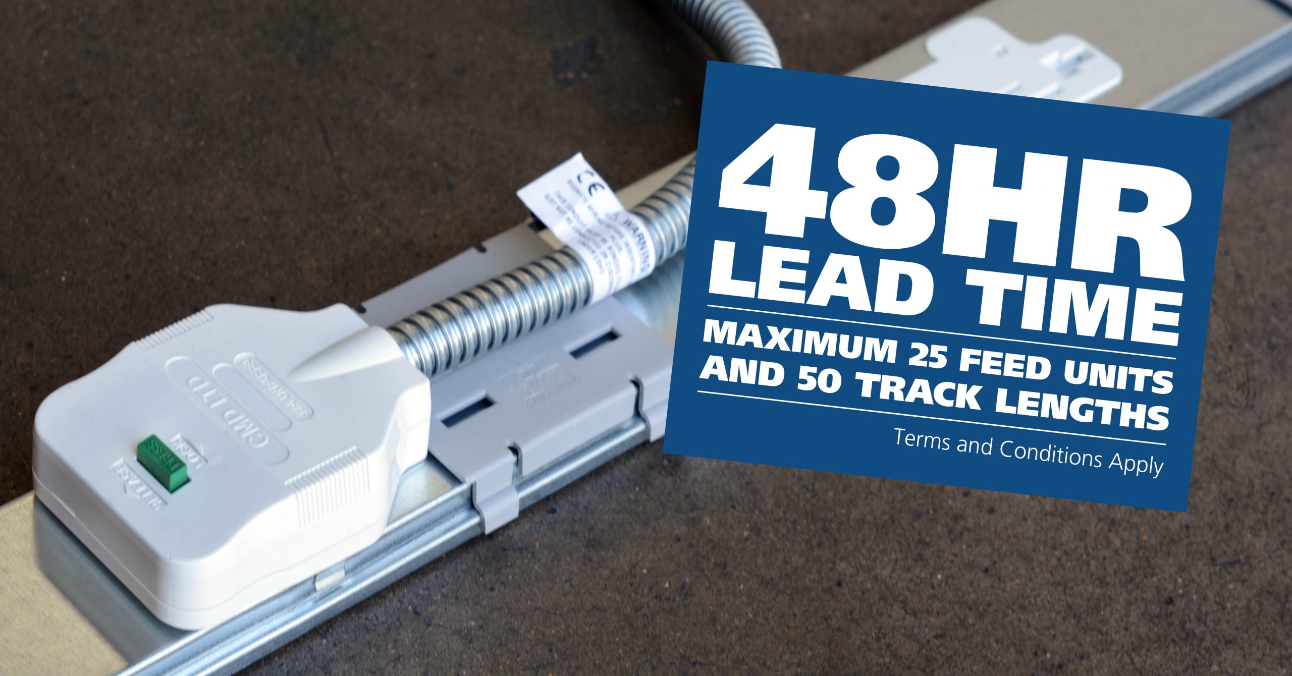
CMD Ltd, the specialist in power distribution systems, workstation power and monitor arms, has launched a rapid ordering service for its Betatrak® underfloor powertrack distribution systems and accessories, with a commitment to delivering within 48-hours of an approved purchase order*. The service enables customers to order up to 50 lengths of Standard or Clean Earth (C/E) low noise Betatrak, along with up to 25 feed...

Read more
CMD INVESTS £1/4 MILLION IN NEW MACHINE AS PART OF FACTORY UPGRADE

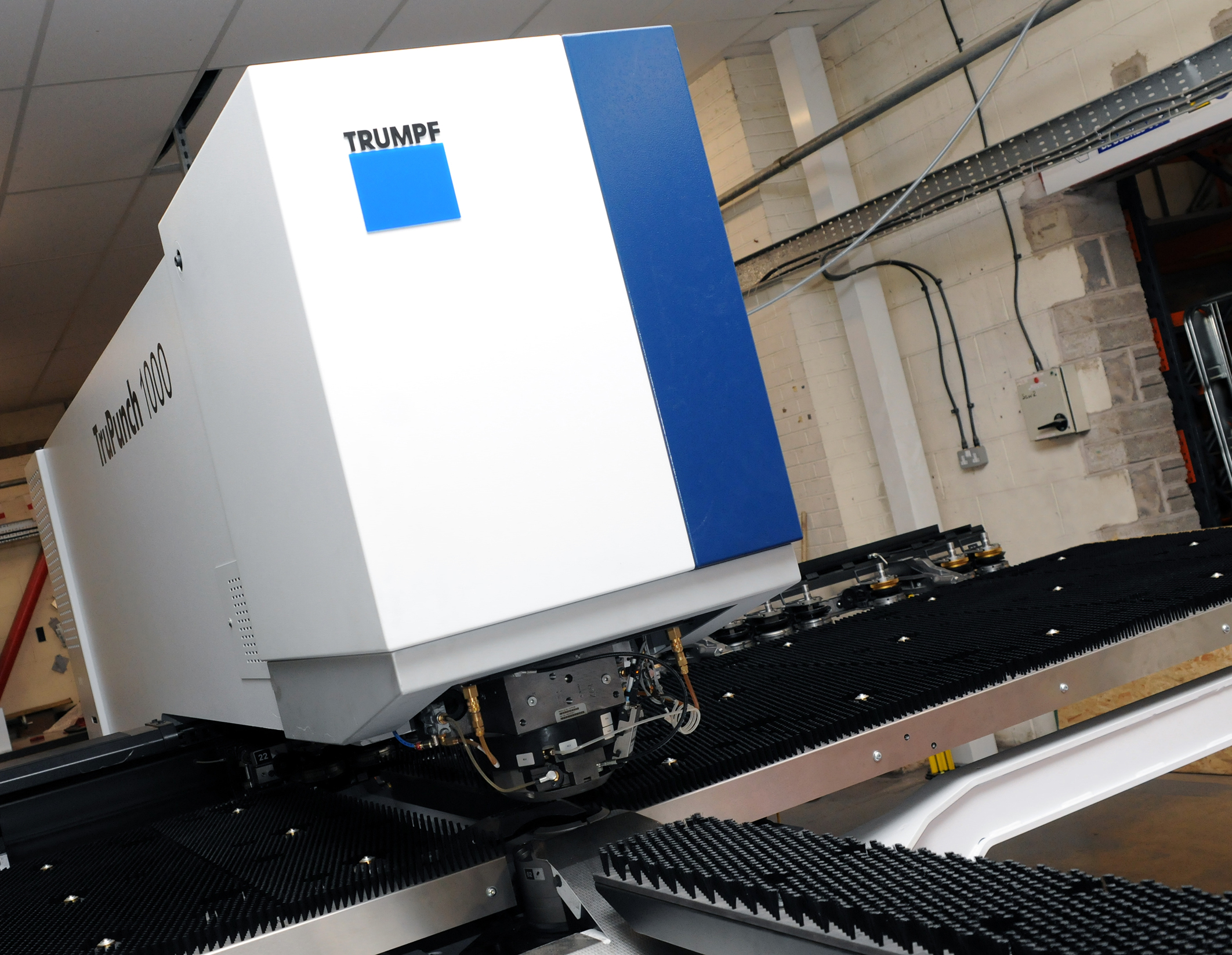
We have invested in a new £1/4m TRUMPF CNC metal punch as part of an asset renewal strategy for our UK manufacturing capability. The new machine will be used in the production of a wide variety of our power distribution systems and workstation power products at our Rotherham factory. Suitable for handling sheet metal between 0.9mm and 3.0mm thick, the new machine will replace one...

Read more
CMD CATALOGUE PROVIDES TECHNICAL POWER DISTRIBUTION GUIDE

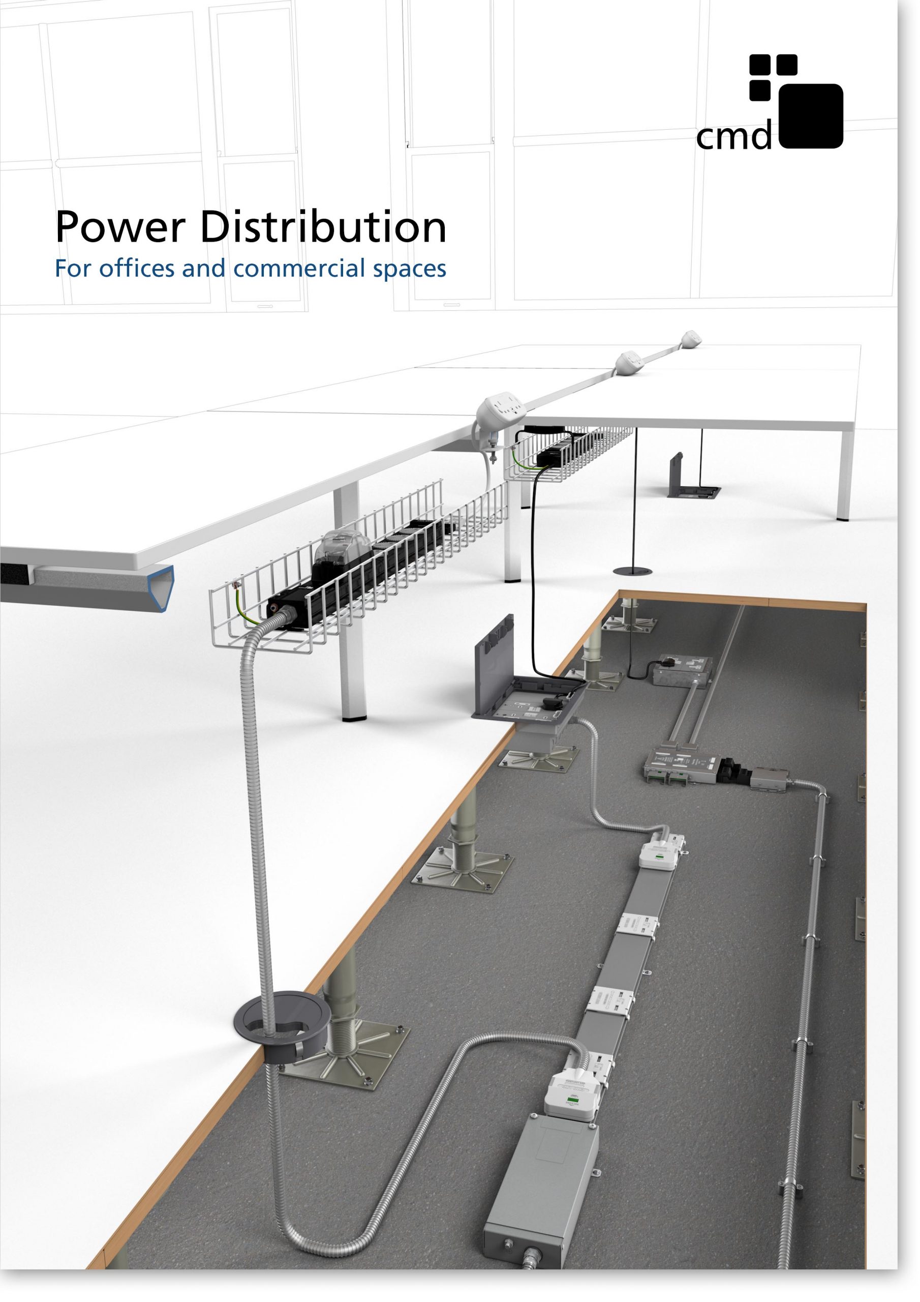
CMD Ltd has released a new catalogue, providing an easy to follow technical guide to our power distribution systems and plug and play desk modules. Detailing CMD’s full range of UK-manufactured power distribution systems and plug and play desk modules, the catalogue will be a helpful source of information to M&E engineers and contractors alike to understand how our power distribution systems connect together and...

Read more
Power Distribution Catalogue
CMD Ltd PLAYS ESSENTIAL ROLE IN ELECTRICAL FIT OUT AT LONDON’S PRESTIGIOUS OFFICE DEVELOPMENT

CMD Ltd, specialist in workplace connectivity and ergonomic solutions, has provided a flexible and high-quality power distribution network for The Ray, a prestigious office development in London’s Farringdon. Well-known for being the former site of The Guardian newspaper, The Ray now stands as an 83,000ft² office development characterised by a modernised warehouse aesthetic, with level two now occupied by a global social media company. The...

Read more

The Ray
CMD plugs in to european opportunity with Schuko Capsule unit launch

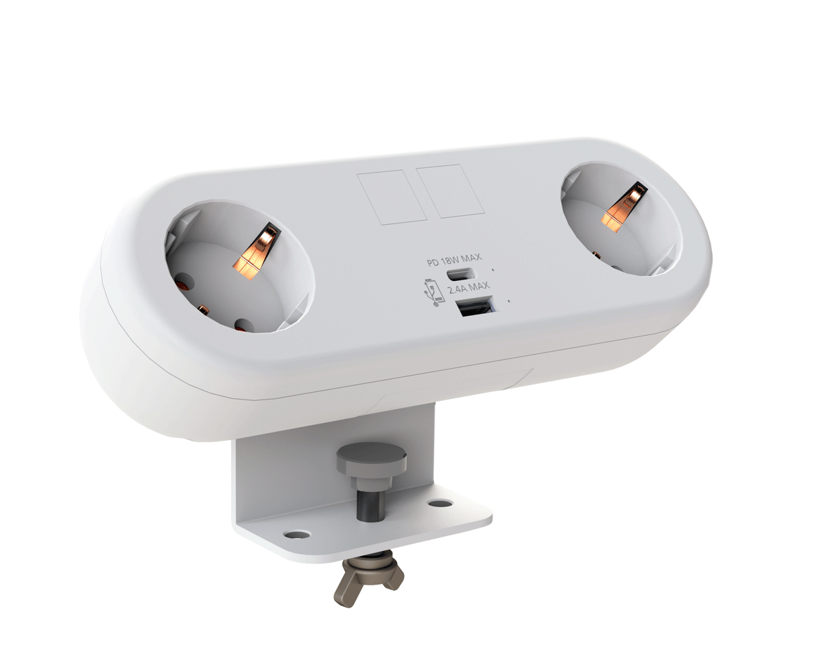
CMD Ltd, the specialist in power and connectivity solutions for commercial environments, has launched a Schuko version of its popular fixed format Capsule workstation power module for export to mainland Europe and beyond. A popular on desk power module comprising two sockets and dual USB (type A and C) chargers, CMD’s Capsule unit is already widely specified in the UK as an off-the-shelf workstation power...

Read more
CMD White Schuko Capsule Desk Power Module
CMD LTD EXTENDS MONITOR ARM RANGE WITH THE LAUNCH OF REACH PLUS

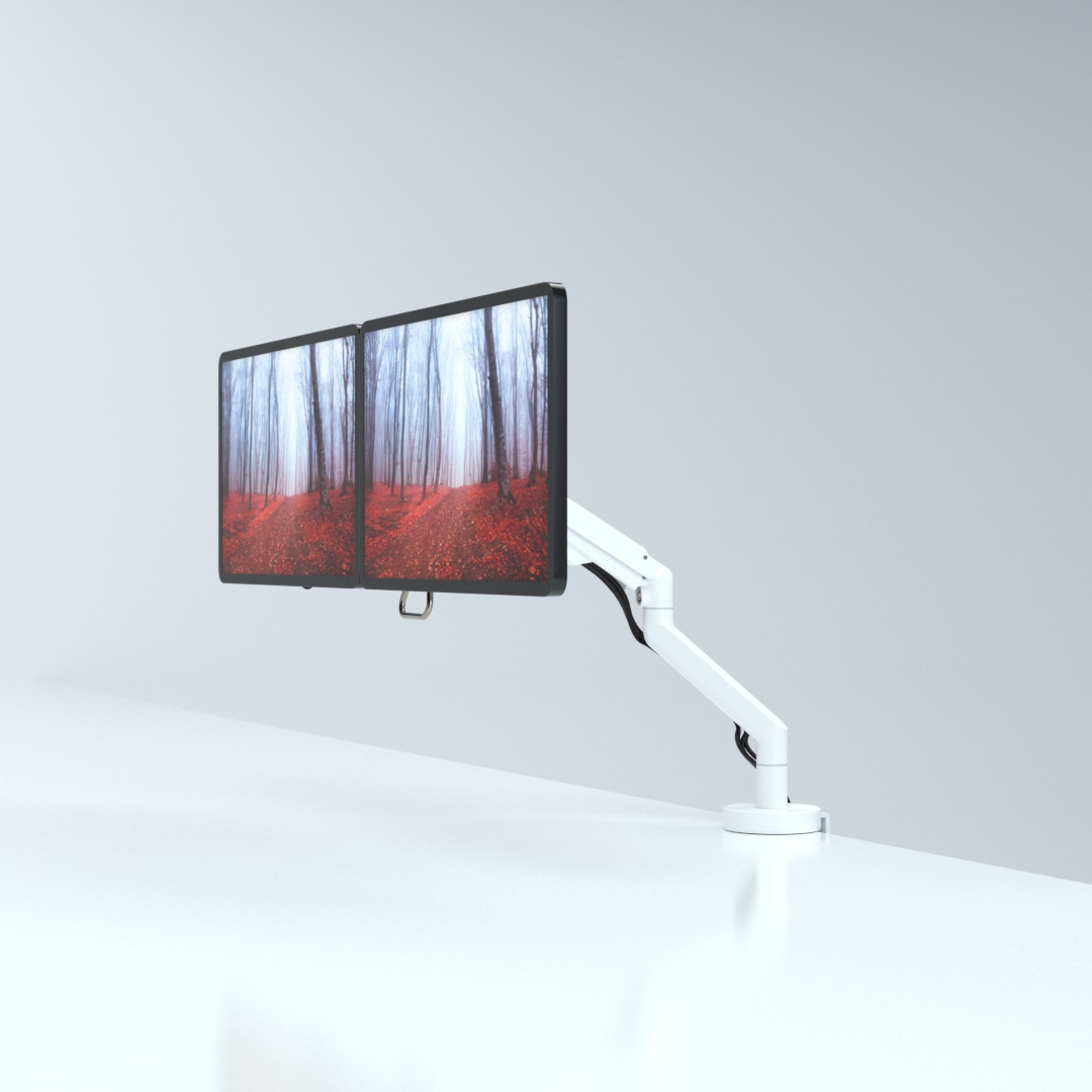
CMD Ltd, the specialist in ergonomic and connectivity solutions for commercial interiors, has completed its Reach monitor arm range with the launch of the Reach Plus. Available in single or dual screen options, the Reach Plus has been designed to provide an ideal solution for both single and dual screen workstation configurations, or can be used with next generation of large format curved screens. Suitable...

Read more
CMD Ltd DEMONSTRATES THE ART OF POWER DISTRIBUTION AT THE UNIVERSITY OF WARWICK

CMD Ltd, the specialist in workplace connectivity and ergonomic solutions, has provided Betatrak busbar power distribution and a range of electrical accessories for two major capital investment projects at the University of Warwick. Designed by Fielden Clegg Bradley Studios, the £33 million Faculty of Arts building is a showpiece development comprising four interconnected structures set around a central atrium, which will enable inter-disciplinary collaboration across...

Read more

University of Warwick
CMD BRINGS HARMONY TO COVENTRY UNIVERSITY RESEARCH FACILITIES

CMD Ltd, the specialist in power distribution solutions and workstation power and ergonomics, has provided under desk and on desk power modules for the refurbishment of three Coventry University research buildings. Located on Coventry University Technology Park, a business park designed to encourage collaboration between the university and knowledge-based businesses, the three buildings are being repurposed as office accommodation for university research teams. The refurbishment...

Read more

Coventry University

What Is an SMT Reflow Oven and How Does It Work?

A Smt Reflow Oven is the controlled heating system behind most modern surface-mount assembly lines. It bonds electronic components to printed circuit boards through carefully managed solder paste. The process looks simple from outside. A board enters on a conveyor, passes through heated zones, and exits with soldered components. Inside, the temperature changes gradually and deliberately.

The oven normally includes preheating, soaking, reflow, and cooling zones. During preheating, moisture and thermal stress are reduced. The soak zone activates the flux and balances temperature across the board. In the reflow zone, solder particles melt briefly, often near the paste manufacturer’s recommended peak temperature. Cooling then solidifies the joints. Small thermocouples attached to test boards help engineers measure the real thermal profile. Not just the display temperature.

Practical experience shows that a successful profile depends on more than oven settings. Board thickness, copper distribution, component size, solder paste, and conveyor speed all influence the result. A large ground plane may absorb heat slowly, while a small component can overheat quickly. Operators often inspect solder joints under magnification and compare results with IPC-based quality guidance. Still, the process is not perfectly predictable. A profile that works well today may need adjustment after a component change or seasonal temperature shift. That limitation matters. Understanding how an Smt Reflow Oven transfers heat helps engineers make safer adjustments, reduce defects, and build more reliable assemblies.

What Is an SMT Reflow Oven and How Does It Work?

What Is an SMT Reflow Oven?

An SMT reflow oven is a controlled heating system used to solder surface-mount components onto printed circuit boards. It does not simply “bake” a board. Instead, it moves the assembly through carefully managed temperature zones. Solder paste first softens, then melts, and finally cools into solid joints. This process connects tiny component terminals with copper pads on the circuit board.

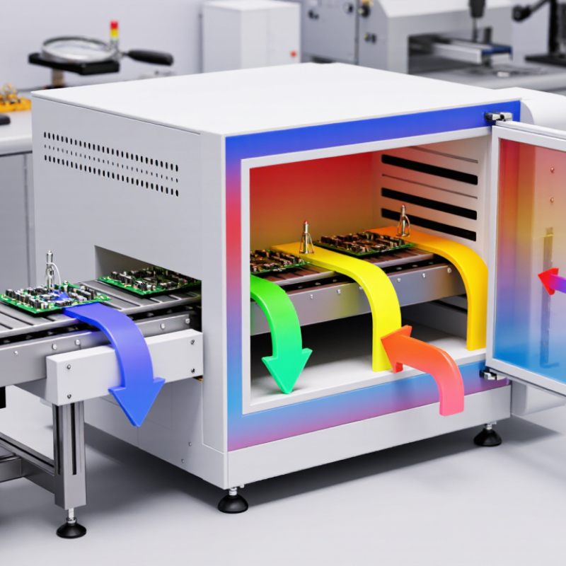
A typical oven includes preheating, soaking, reflow, and cooling zones. In the preheat area, the board temperature rises gradually, reducing thermal shock. The soaking zone helps spread heat through different materials and activates the paste chemistry. During reflow, the solder passes its melting point for a controlled period. Cooling then forms the final joint. Conveyor speed, airflow, zone temperatures, and board loading all affect the result.

Small details matter. A thermocouple attached near a large connector can reveal uneven heating that the oven display misses. Too much heat may damage components or warp the board. Too little heat can create weak, dull, or incomplete joints. A profile that works for one board may fail on another. That is why technicians compare measured profiles with solder paste data and component limits. The process is reliable, but not automatic. Even a well-maintained oven needs regular inspection, calibration, and human judgment. Some production teams rely too heavily on preset recipes, which is convenient but worth questioning.

Core Components and Their Functions

An SMT reflow oven heats solder paste until components bond with printed circuit boards. Its core system has several controlled zones.

Preheat zones raise the board gradually and reduce thermal shock.

Soaking zones activate flux and equalize component temperatures.

Reflow zones push solder above its liquidus point.

Cooling zones then solidify the joints under controlled conditions.

Conveyors set board speed and keep orientation stable. Heating elements provide energy, while fans circulate hot air across dense assemblies. Thermocouples measure real board temperatures, not just chamber settings. A programmable controller records the thermal profile for process verification. Exhaust systems remove flux vapors. Nitrogen systems can reduce oxidation, although they add operating cost.

A 2024 market analysis by MarketsandMarkets estimates steady growth in SMT equipment demand through the decade. That trend reflects tighter miniaturization and higher production volumes. Yet market growth does not guarantee better solder joints. Poor profiling still causes defects.

Tips:

Attach thermocouples to large, small, and heat-sensitive components. Compare the measured profile with solder-paste specifications. Check conveyor rails before production. Even a slight width error can shift a board. IPC process guidance recommends profiling across representative assemblies, not only empty fixtures. In practice, operators often trust the oven display too much. That assumption deserves checking. Profile records should include date, board type, paste lot, and operator initials. This small discipline improves traceability. Keep reviewing it.

How PCB Assemblies Move Through the Oven

What Is an SMT Reflow Oven and How Does It Work?

How PCB Assemblies Move Through the Oven

An SMT reflow oven heats a PCB assembly in controlled stages. Before heating begins, a conveyor carries each board through the chamber at a steady speed. Small rails support the panel edges. This prevents contact with wet solder paste and placed components. The conveyor speed must match the selected thermal profile. A slight change can affect solder quality.

Inside the oven, the assembly passes through preheat, soak, reflow, and cooling zones. Preheat raises the board temperature gradually. This reduces thermal shock and helps solvents escape from the solder paste. The soak zone balances heat across large copper areas and small components. Reflow then pushes the solder above its melting point. Molten solder forms reliable joints around component terminals. Cooling follows in a controlled manner.

The process is not perfectly uniform. Thick copper planes may heat more slowly than nearby pads. Experienced technicians attach temperature sensors to test boards and compare real readings with the target profile. They also check conveyor alignment, airflow, and zone temperatures during routine production. A profile that worked yesterday may drift after maintenance or seasonal changes. That possibility deserves attention. Visual inspection can reveal bridges, insufficient solder, or shifted parts, but it cannot show every hidden weakness. Careful measurement remains essential.

What Is an SMT Reflow Oven and How Does It Work? — How PCB Assemblies Move Through the Oven

Process Stage Typical Temperature Range Typical Time or Speed What Happens to the PCB Assembly Main Process Variables Typical Control or Inspection Point
1. Loading and Conveyor Entry 20–30°C Conveyor speed commonly set between 0.5 and 1.5 m/min The populated PCB enters the oven on a mesh conveyor or edge-support rail. The board is carried through the heating zones at a controlled and constant speed. Board width, conveyor speed, board support, panel orientation, and clearance from the oven walls Confirm that the PCB is stable, correctly supported, and suitable for the selected profile.
2. Preheat 25–150°C Usually 60–120 seconds The assembly temperature rises gradually. This reduces thermal shock and begins activating the flux in the solder paste. Heating rate, commonly about 0.5–2.0°C/s; board mass; component mix; and flux formulation Measure the temperature ramp to help prevent board warpage, component stress, and solder paste spatter.
3. Soak or Flux Activation 140–180°C Typically 60–120 seconds The board remains within a controlled temperature band. Solvents evaporate, flux activates, and temperature differences across the PCB are reduced before melting begins. Soak temperature, soak duration, flux chemistry, and temperature uniformity across the board Check that the board reaches the required soak window without excessive oxidation or premature solder melting.
4. Ramp to Reflow 180–217°C for lead-free solder Often 30–90 seconds The PCB moves into higher-temperature zones. The solder paste approaches its melting point while the components and board continue heating evenly. Ramp rate, commonly limited to approximately 0.5–1.5°C/s; peak preparation; and thermal uniformity Verify that the temperature rise is controlled to reduce solder balling, component cracking, and tombstoning.
5. Reflow or Liquidus Zone Above 217°C for lead-free solder; commonly 230–250°C peak Time above liquidus commonly 45–90 seconds The solder particles melt and form liquid solder joints. Surface tension helps center many components while the molten solder wets component terminals and PCB pads. Peak temperature, time above liquidus, solder paste alloy, pad finish, component limits, and oxygen level Use a thermocouple-based profile to confirm adequate wetting without exceeding the temperature rating of components or the PCB.
6. Controlled Cooling Approximately 217°C down to below 100°C Common cooling rate: about 1–4°C/s The molten solder solidifies and creates mechanical and electrical connections. Controlled cooling helps establish a consistent solder-joint structure. Cooling rate, airflow, board thickness, component density, and solder alloy Monitor cooling to limit thermal stress, solder-joint defects, and excessive intermetallic growth.
7. Oven Exit and Unloading Typically below 100°C Continuous conveyor transfer The assembled PCB leaves the heated zones. It is allowed to cool further before handling, stacking, testing, or additional assembly operations. Exit temperature, handling time, board support, and cooling airflow Check for visible solder bridges, insufficient solder, lifted leads, misplaced components, and board deformation.
8. Post-Reflow Verification Room temperature Performed after the board is safe to handle The soldered assembly is inspected to verify that the thermal profile produced reliable joints and that components remained correctly positioned. Inspection criteria, solder-joint appearance, component polarity, voiding, and process traceability Typical methods include automated optical inspection, X-ray inspection for hidden joints, electrical testing, and profile-data review.
Note: The values shown are typical process ranges for lead-free SMT reflow and must be adjusted according to the solder paste manufacturer’s profile window, PCB construction, component temperature ratings, and product-specific quality requirements.

How the Reflow Temperature Profile Works

An SMT reflow oven heats a populated circuit board through controlled temperature zones. The temperature profile is the oven’s practical blueprint. It shows how quickly the board heats, how long solder remains active, and how gently it cools.

During preheat, the board rises gradually, often around 1–3°C per second. A steady ramp helps reduce thermal shock and prevents solder paste from splattering. The soak zone allows solvents to evaporate and equalizes temperatures across heavy and light components. This stage is easy to underestimate. A large connector may still be cool while a small pad is already ready for reflow.

The reflow zone pushes the solder above its liquidus temperature. Many lead-free alloys require a peak near 235°C, but the paste specification remains the real reference. Time above liquidus must be long enough for reliable wetting, not unnecessarily long. Cooling should also be controlled, because rapid drops can stress solder joints and ceramic parts. In production, technicians attach thermocouples to the board’s hottest and coldest locations, then compare the measured curve with the paste supplier’s limits. Conveyor speed and zone settings are adjusted together. One setting rarely fixes everything. A profile can look acceptable and still produce dull joints, voids, or uneven wetting. That is why experienced engineers inspect both the graph and the actual soldered board.

Factors That Affect Soldering Quality

What Is an SMT Reflow Oven and How Does It Work?

Factors That Affect Soldering Quality

An SMT reflow oven heats assembled circuit boards through controlled thermal zones. The board moves on a conveyor. Preheat removes thermal shock, soak activates flux, and reflow melts the solder paste. Cooling then forms reliable joints. For lead-free SAC alloys, solder melts near 217°C. IPC-7530 recommends measuring the real board profile, not trusting the oven display alone.

Temperature control strongly affects soldering quality. A peak temperature commonly falls between 235°C and 250°C. The time above liquidus is often kept near 45–90 seconds. Excessive time can damage components or consume flux. Insufficient time may leave dull, weak joints. Small boards heat differently from large ground planes. This difference is easy to overlook.

Solder paste condition matters too. Moisture, storage time, stencil design, and printing pressure change deposit volume. J-STD-033 handling guidance links moisture exposure with package cracking during reflow. Oxygen also influences wetting and oxidation; many production lines monitor it below 1,000 ppm when using nitrogen. That target is not universal. It depends on paste chemistry and joint design. In practice, technicians should confirm results through profiling, visual inspection, and X-ray checks. A perfect profile can still fail when paste volume is uneven. That is the uncomfortable part.

What Is an SMT Reflow Oven and How Does It Work?

An SMT reflow oven heats a populated PCB through controlled thermal zones to melt solder paste, form reliable joints, and cool the assembly without excessive thermal stress.

Factors That Affect Soldering Quality

This typical lead-free reflow profile uses a peak temperature near 240°C and keeps the assembly above the 217°C liquidus point for approximately 45–90 seconds. Excessive heating rates, insufficient time above liquidus, an overly high peak temperature, or rapid cooling can cause defects such as tombstoning, poor wetting, voids, and component damage. Actual settings should be verified with a thermocouple-based profile test.