

News

Miro: A New Standard in Responsible Innovation

Miro: A New Standard in Responsible Innovation The Miro monitor arm is setting new benchmarks in sustainability. It offers a high-performance solution without compromising on environmental responsibility. Designed with careful material selection, local sourcing, and longevity in mind, Miro’s responsible approach to design and unique manoeuvrability set it apart from the competition. Sustainable Choices Miro is crafted from energy-efficient materials with a lower carbon impact....

Read more
HSE Advisor

Role Purpose Support in the development, implementation and maintenance of the company’s Health, Safety & Environmental policies, processes, operational procedures, and standards.  Ensuring best practice and championing a continually improving HSE culture within the business. Key Responsibilities Liaise with and provide support to all areas of the business to eliminate, mitigate or reduce identified HSE exposures. Partner with the production management team and team leaders,...

Read more
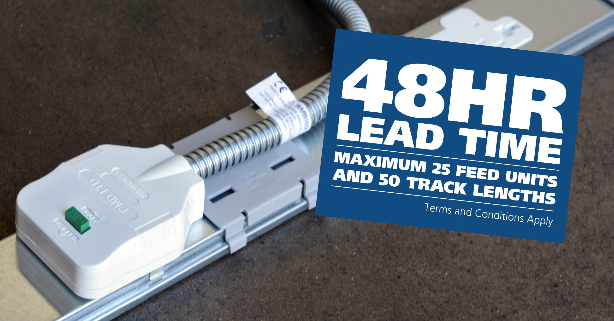
CMD Ltd LAUNCHES 48-HOUR TURNAROUND ON BETATRAK® RAPID ORDERING SERVICE

CMD Ltd, the specialist in power distribution systems, workstation power and monitor arms, has launched a rapid ordering service for its Betatrak® underfloor powertrack distribution systems and accessories, with a commitment to delivering within 48-hours of an approved purchase order*. The service enables customers to order up to 50 lengths of Standard or Clean Earth (C/E) low noise Betatrak, along with up to 25 feed...

Read more
CMD INVESTS £1/4 MILLION IN NEW MACHINE AS PART OF FACTORY UPGRADE

We have invested in a new £1/4m TRUMPF CNC metal punch as part of an asset renewal strategy for our UK manufacturing capability. The new machine will be used in the production of a wide variety of our power distribution systems and workstation power products at our Rotherham factory. Suitable for handling sheet metal between 0.9mm and 3.0mm thick, the new machine will replace one...

Read more

CMD CATALOGUE PROVIDES TECHNICAL POWER DISTRIBUTION GUIDE

CMD Ltd has released a new catalogue, providing an easy to follow technical guide to our power distribution systems and plug and play desk modules. Detailing CMD’s full range of UK-manufactured power distribution systems and plug and play desk modules, the catalogue will be a helpful source of information to M&E engineers and contractors alike to understand how our power distribution systems connect together and...

Read more
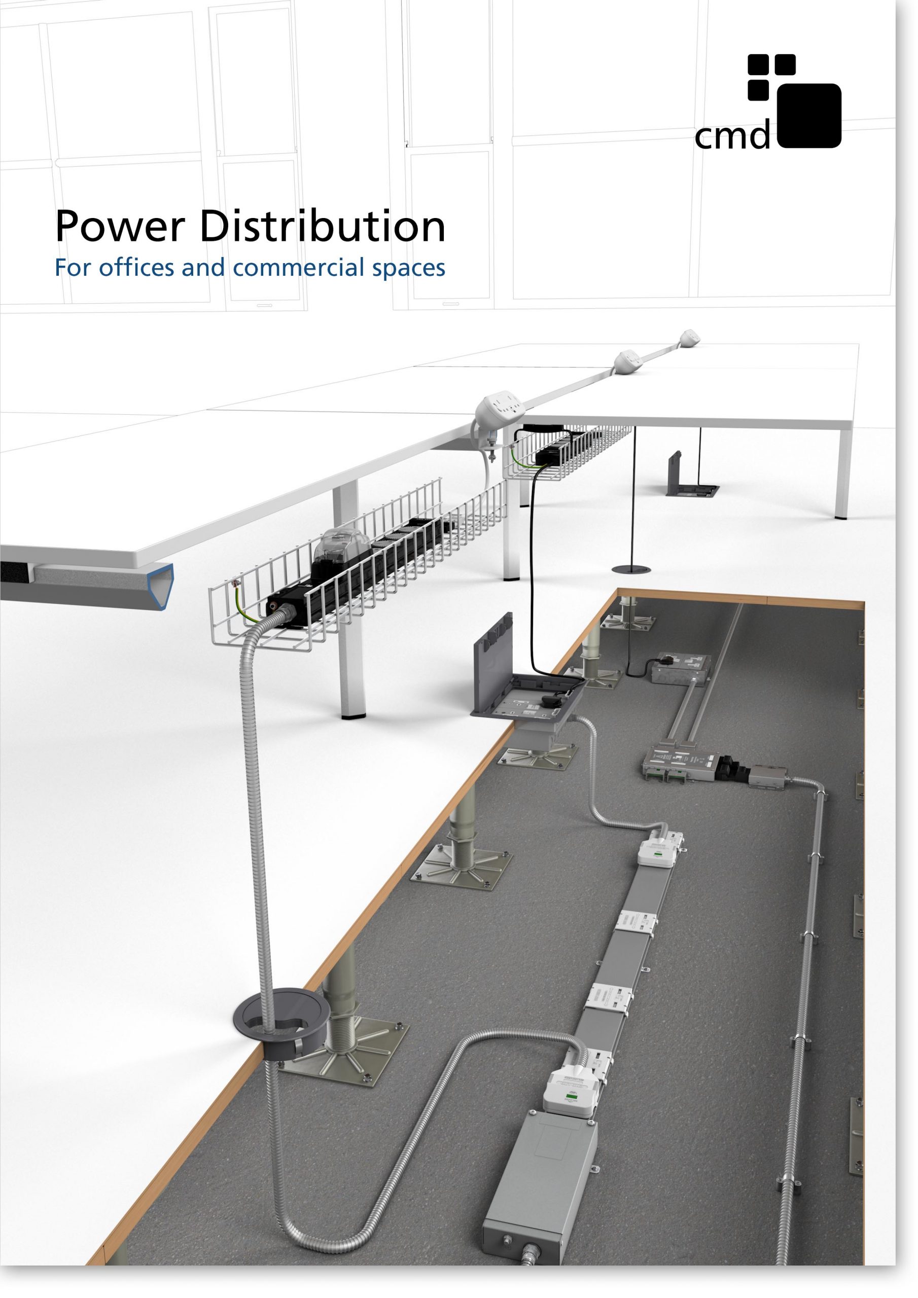
Power Distribution Catalogue
CMD Ltd PLAYS ESSENTIAL ROLE IN ELECTRICAL FIT OUT AT LONDON’S PRESTIGIOUS OFFICE DEVELOPMENT

CMD Ltd, specialist in workplace connectivity and ergonomic solutions, has provided a flexible and high-quality power distribution network for The Ray, a prestigious office development in London’s Farringdon. Well-known for being the former site of The Guardian newspaper, The Ray now stands as an 83,000ft² office development characterised by a modernised warehouse aesthetic, with level two now occupied by a global social media company. The...

Read more

The Ray
CMD plugs in to european opportunity with Schuko Capsule unit launch

CMD Ltd, the specialist in power and connectivity solutions for commercial environments, has launched a Schuko version of its popular fixed format Capsule workstation power module for export to mainland Europe and beyond. A popular on desk power module comprising two sockets and dual USB (type A and C) chargers, CMD’s Capsule unit is already widely specified in the UK as an off-the-shelf workstation power...

Read more
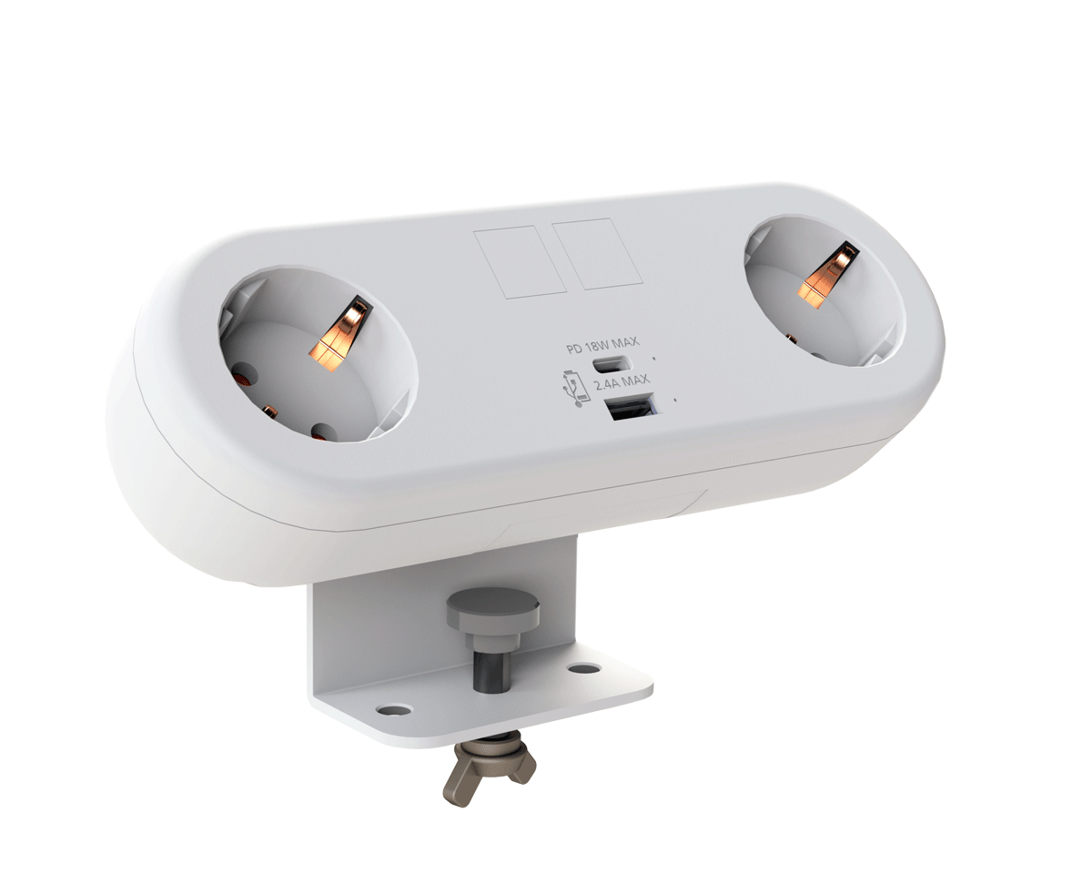
CMD White Schuko Capsule Desk Power Module
CMD LTD EXTENDS MONITOR ARM RANGE WITH THE LAUNCH OF REACH PLUS

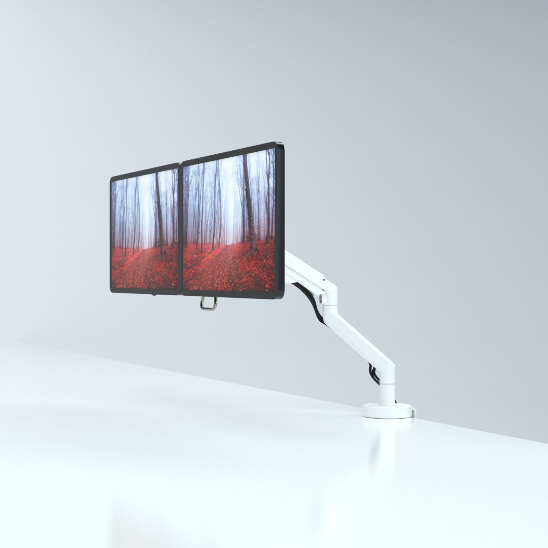
CMD Ltd, the specialist in ergonomic and connectivity solutions for commercial interiors, has completed its Reach monitor arm range with the launch of the Reach Plus. Available in single or dual screen options, the Reach Plus has been designed to provide an ideal solution for both single and dual screen workstation configurations, or can be used with next generation of large format curved screens. Suitable...

Read more
CMD Ltd DEMONSTRATES THE ART OF POWER DISTRIBUTION AT THE UNIVERSITY OF WARWICK

CMD Ltd, the specialist in workplace connectivity and ergonomic solutions, has provided Betatrak busbar power distribution and a range of electrical accessories for two major capital investment projects at the University of Warwick. Designed by Fielden Clegg Bradley Studios, the £33 million Faculty of Arts building is a showpiece development comprising four interconnected structures set around a central atrium, which will enable inter-disciplinary collaboration across...

Read more

University of Warwick
CMD BRINGS HARMONY TO COVENTRY UNIVERSITY RESEARCH FACILITIES

CMD Ltd, the specialist in power distribution solutions and workstation power and ergonomics, has provided under desk and on desk power modules for the refurbishment of three Coventry University research buildings. Located on Coventry University Technology Park, a business park designed to encourage collaboration between the university and knowledge-based businesses, the three buildings are being repurposed as office accommodation for university research teams. The refurbishment...

Read more

Coventry University

How to Choose a PCB Terminal Block?

Choosing a Pcb Terminal Block is not just a matter of matching its pin spacing to a board. The right choice must suit the circuit, wire type, assembly method, and conditions where the equipment will operate. A block that looks compact on a drawing may leave too little room for a screwdriver or neighboring components. Small details matter.

This guide introduces the main checks behind a reliable selection. It considers rated voltage and current, wire range, pitch, number of positions, and mounting style. It also explains why datasheet ratings need context: temperature rise, conductor size, and nearby heat sources can affect real operating performance. A rating alone is not a guarantee. Inspect the PCB footprint and verify that the terminal’s pins fit the board layout before ordering production quantities. If possible, test a sample with the intended wire and tool; a connection that feels secure in a bench check can still expose clearance or assembly problems later.

Material, environment, and maintenance deserve attention too. Vibration, dust, moisture, and repeated wiring changes may influence the housing and contact design you need. There is rarely one best terminal block for every project. Even experienced designers can overlook a practical constraint when comparing catalog tables, so leave room to question an apparently perfect match. The following outline helps you compare options with measurable requirements, rather than choosing by appearance or price alone.

How to Choose a PCB Terminal Block?

Understand PCB Terminal Block Types and How They Work

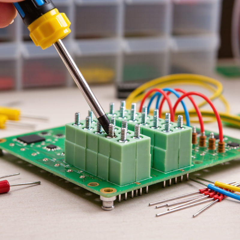
A PCB terminal block connects field wiring to copper tracks on a circuit board. Its metal contacts carry current, while the housing keeps conductors separated and supported. Screw-clamp types use a screw to press each wire against a conductive plate. They offer a firm connection, but overtightening can damage fine strands or the clamp.

Spring-clamp blocks hold wires with a spring. An installer presses a release point, inserts the stripped conductor, then lets the spring secure it. Push-in versions accept compatible solid wires directly, which can speed assembly. Pluggable terminal blocks have two parts: a board-mounted header and a removable wire connector. This makes servicing easier, though the plug must be fully seated. Small details matter.

Blocks also differ by pitch, wire-entry direction, number of poles, and mounting style. A vertical entry may fit a narrow enclosure, while a horizontal entry can make wiring easier to reach. Check the rated current, voltage, wire range, temperature limits, and PCB footprint against the actual design. A rating alone is not enough; board spacing and heat buildup matter too. It is easy to focus on the clamp and overlook the solder pins. Review the manufacturer’s technical drawings, then verify fit and wire retention in a sample assembly. No single connection style is best for every board.

Define Electrical and Environmental Requirements

A PCB terminal block should match the circuit’s real operating conditions, not just its nominal voltage. Record the maximum continuous current, expected voltage, wire size, and available board space before comparing options. A 5-amp circuit may need a higher-rated terminal block if heat, tight spacing, or nearby components raise operating temperature. Check the manufacturer’s derating curves and confirm the conductor range fits the wire you plan to use.

Tips: Leave room for a screwdriver and wire bend. Check pitch against the PCB layout. Small details matter.

Next, define the environment around the finished assembly. Note temperature swings, vibration, moisture, dust, and exposure to cleaning chemicals. A terminal block’s published temperature range is useful, but nearby heat sources can change conditions at the connection. For outdoor or washdown equipment, assess protection at the enclosure level; an open terminal block does not create a sealed assembly. Review the datasheet for mounting and retention details, especially where cables may be pulled or shaken. If the environment is uncertain, document the assumption and test a sample under realistic conditions. That extra check can reveal a poor fit before the PCB design is fixed.

How to Choose a PCB Terminal Block? - Define Electrical and Environmental Requirements

Requirement What to Define Practical Selection Guidance What to Verify
Operating voltage Nominal and maximum working voltage, AC or DC, and transient conditions. Choose a block with a rated voltage suitable for the complete circuit and its applicable safety standard. Do not treat a nominal rating as a substitute for surge assessment. Voltage rating, pollution degree, overvoltage category, and required creepage and clearance distances in the end product.
Current and heating Continuous current per pole, simultaneous loading, and expected ambient temperature. Use the manufacturer’s rated current and derating data. Closely spaced poles, high ambient temperature, and limited PCB copper can increase temperature rise. Current rating conditions, temperature-rise data, PCB copper requirements, and performance with adjacent poles loaded.
Wire size and connection Conductor material, solid or stranded construction, wire cross-section, and termination method. Match the terminal’s accepted wire range to the actual conductor. Screw-clamp, spring-clamp, and push-in designs have different wiring and maintenance characteristics. Permitted wire range, strip length, ferrule compatibility, tightening torque where applicable, and wire-pull requirements.
Pole count and pitch Number of circuits, center-to-center pitch, board-edge access, and available board area. Select a pitch that fits the PCB layout and provides adequate spacing for the circuit voltage and applicable safety requirements. Footprint dimensions, pin spacing, board-edge clearance, terminal orientation, and required electrical spacing.
PCB attachment and layout Through-hole or surface-mount assembly, mechanical loads, PCB thickness, and copper layout. Through-hole pins are common for wire-entry terminal blocks. Confirm the PCB can support insertion, wiring, and service forces without excessive stress. Recommended land pattern, hole size, soldering process, retention features, and mechanical test conditions.
Temperature range Minimum and maximum ambient temperature, local heat sources, and operating duration. Choose a component whose specified operating range covers the real enclosure conditions, including self-heating and nearby components. Operating-temperature rating, insulation material limits, and current derating at elevated temperature.
Moisture, dust, and contamination Indoor or outdoor use, condensation risk, dust exposure, and chemical contaminants. Many PCB terminal blocks have exposed connection openings. Use an enclosure or other system-level protection when the installation requires protection from moisture or dust. Protection rating of the completed assembly, condensation controls, material compatibility, and corrosion requirements.
Vibration and shock Expected vibration level, shock exposure, mounting orientation, and cable movement. For mobile or vibration-prone equipment, consider a connection system with suitable retention and validate the complete PCB assembly under representative conditions. Vibration and shock test data, wire retention, screw-locking provisions if applicable, and PCB mechanical support.
Safety and compliance Product market, applicable end-product standards, flammability requirements, and touch protection. Assess the terminal block as part of the final equipment. Component approvals alone do not establish compliance of the completed product. Relevant certifications, insulation and flammability information, accessibility of live parts, and end-product evaluation requirements.

Ratings and suitability depend on the specific terminal block, PCB design, installation conditions, and applicable standards. Confirm critical values in the component documentation and validate the finished assembly.

Choose Mounting Style, Pitch, and Wire Connection Method

Choose the mounting style around the board layout and service needs. Through-hole blocks suit robust assemblies and thicker boards; surface-mount versions save underside space but need careful solder-process control. A detachable plug can speed field replacement, while a fixed block reduces parts and mating interfaces. Small details matter. Check the drawing.

Pitch sets how closely adjacent poles sit, but the smallest option is not automatically best. Leave room for the wire insulation, screwdriver access, and expected voltage and current. Grand View Research’s 2023 printed circuit board market report valued the global market at USD 76.12 billion, reflecting the scale of modern board production. That figure is not a design rule; it does remind us that compact layouts are common. Still, squeezing terminals together can make assembly and inspection awkward.

Match the wire connection to the conductor and installation conditions. Screw clamps tolerate a broad range of wire sizes, but torque consistency matters. Spring-clamp designs can reduce retightening needs, while push-in connections work best with compatible solid or ferruled wire. Check the rated wire range, strip length, current, and temperature rise in the manufacturer’s technical data. Not always obvious. I have seen a suitable-looking block fail the fit check because the screwdriver could not reach its clamp after enclosure assembly. Verify the complete stack-up before locking the footprint.

Check Safety Ratings, Materials, and PCB Compatibility

How to Choose a PCB Terminal Block?

A PCB terminal block must suit the circuit, board layout, and installation environment. Check its rated voltage and current, wire range, pitch, and operating temperature. IEC 60947-7-1 sets requirements and test methods for terminal blocks used with copper conductors. UL 94’s V-0 vertical-burning criteria limit afterflame to 10 seconds after each flame application. However, a V-0 housing rating alone does not certify the complete terminal block or its suitability for your equipment.

Inspect contact material and plating, housing material, and the manufacturer’s temperature-derating data. Then compare pin dimensions with the PCB footprint, copper pads, and soldering process. A block can match the schematic yet interfere with nearby components or board edges. It is easy to miss. Review required creepage and clearance distances for the actual voltage and pollution environment, rather than relying on pitch alone.

Tip: Test a sample on your board. Check wire insertion, screw access, solder joints, and fit after assembly. Record the exact part ratings and test conditions; a rating without its conditions can mislead. If the installation is vibration-prone, verify retention and vibration-test information instead of assuming a tight screw is enough.

Evaluate Assembly, Testing, and Maintenance Needs

How to Choose a PCB Terminal Block?
Evaluate Assembly, Testing, and Maintenance Needs

A terminal block should fit the way the board is built and serviced, not just its electrical rating. Check its pitch against nearby components and confirm that operators can reach the screw with the selected tool. A few millimeters can make a difference. For automated assembly, review the block’s footprint, pin alignment, and seating stability. For hand assembly, consider whether wires can be inserted without bending adjacent parts. These details are easy to overlook during a desk review.

Tips: Check wire-entry direction, screwdriver clearance, and replacement access on a physical sample. Verify specified tightening torque. Leave room for test probes. If the assembly feels awkward, revisit the layout before production.

Plan tests around real use. Measure continuity and inspect solder joints after assembly; then apply a suitable wire pull test using a documented method. If the product may face vibration or temperature changes, assess those conditions too. Record results and keep sample boards for comparison. Maintenance matters as well: a removable block can simplify replacement, but only if technicians can release it without stressing the PCB. I have seen compact layouts save board space yet slow repairs. That trade-off deserves a real review, not an assumption. Follow the component specifications and the project’s test limits.