

News

Miro: A New Standard in Responsible Innovation

Miro: A New Standard in Responsible Innovation The Miro monitor arm is setting new benchmarks in sustainability. It offers a high-performance solution without compromising on environmental responsibility. Designed with careful material selection, local sourcing, and longevity in mind, Miro’s responsible approach to design and unique manoeuvrability set it apart from the competition. Sustainable Choices Miro is crafted from energy-efficient materials with a lower carbon impact....

Read more
HSE Advisor

Role Purpose Support in the development, implementation and maintenance of the company’s Health, Safety & Environmental policies, processes, operational procedures, and standards.  Ensuring best practice and championing a continually improving HSE culture within the business. Key Responsibilities Liaise with and provide support to all areas of the business to eliminate, mitigate or reduce identified HSE exposures. Partner with the production management team and team leaders,...

Read more
CMD Ltd LAUNCHES 48-HOUR TURNAROUND ON BETATRAK® RAPID ORDERING SERVICE

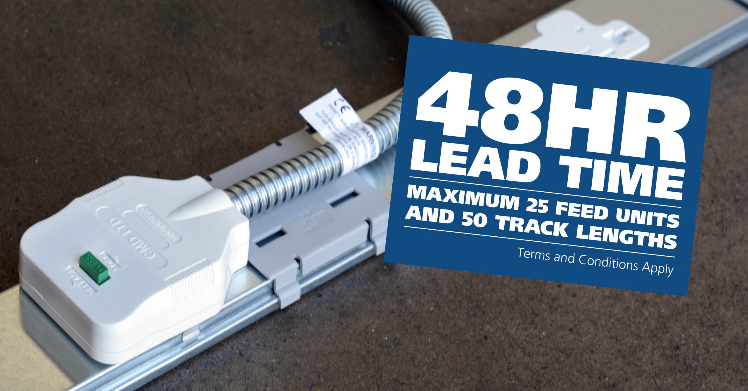
CMD Ltd, the specialist in power distribution systems, workstation power and monitor arms, has launched a rapid ordering service for its Betatrak® underfloor powertrack distribution systems and accessories, with a commitment to delivering within 48-hours of an approved purchase order*. The service enables customers to order up to 50 lengths of Standard or Clean Earth (C/E) low noise Betatrak, along with up to 25 feed...

Read more
CMD INVESTS £1/4 MILLION IN NEW MACHINE AS PART OF FACTORY UPGRADE

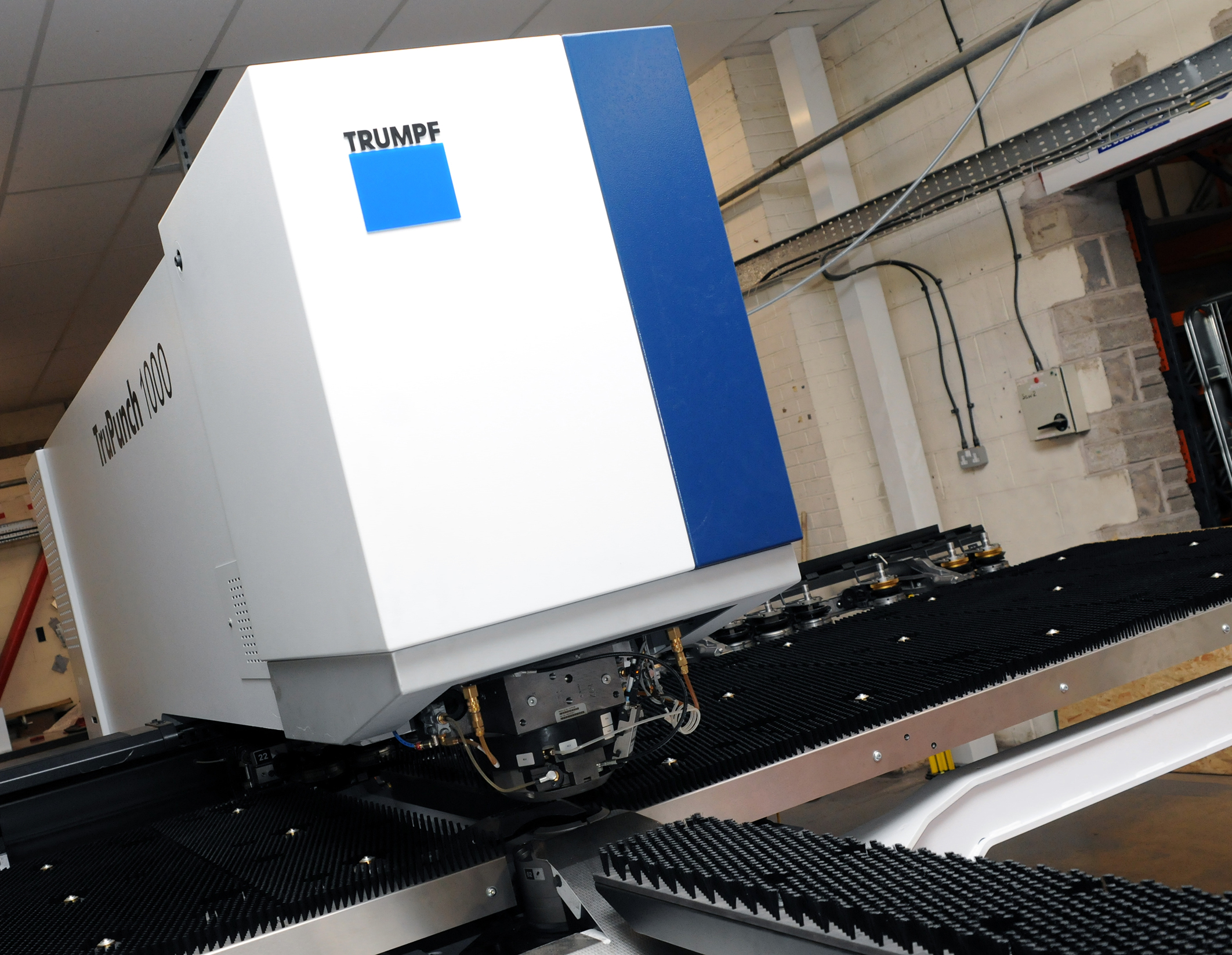
We have invested in a new £1/4m TRUMPF CNC metal punch as part of an asset renewal strategy for our UK manufacturing capability. The new machine will be used in the production of a wide variety of our power distribution systems and workstation power products at our Rotherham factory. Suitable for handling sheet metal between 0.9mm and 3.0mm thick, the new machine will replace one...

Read more
CMD CATALOGUE PROVIDES TECHNICAL POWER DISTRIBUTION GUIDE

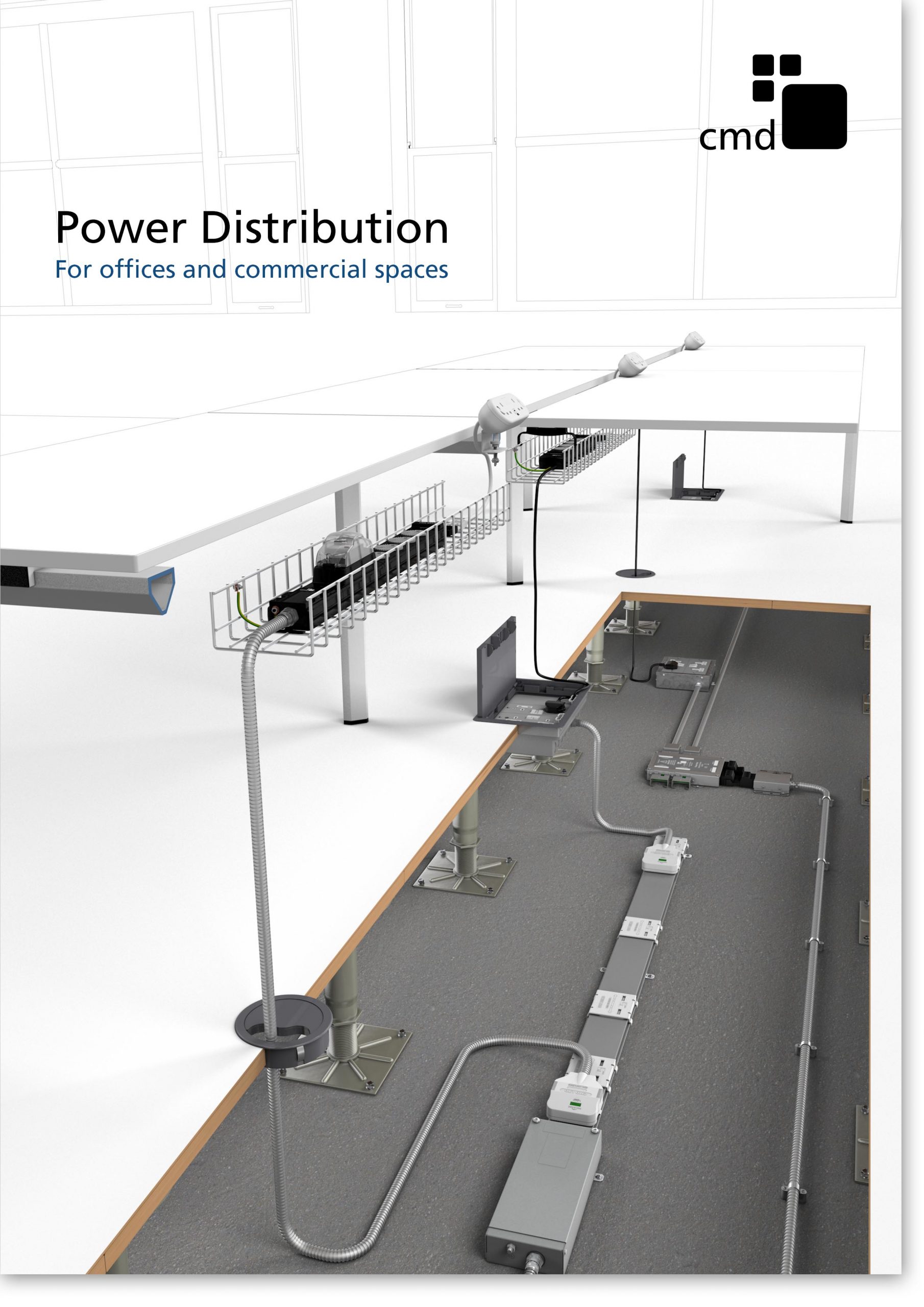
CMD Ltd has released a new catalogue, providing an easy to follow technical guide to our power distribution systems and plug and play desk modules. Detailing CMD’s full range of UK-manufactured power distribution systems and plug and play desk modules, the catalogue will be a helpful source of information to M&E engineers and contractors alike to understand how our power distribution systems connect together and...

Read more
Power Distribution Catalogue
CMD Ltd PLAYS ESSENTIAL ROLE IN ELECTRICAL FIT OUT AT LONDON’S PRESTIGIOUS OFFICE DEVELOPMENT

CMD Ltd, specialist in workplace connectivity and ergonomic solutions, has provided a flexible and high-quality power distribution network for The Ray, a prestigious office development in London’s Farringdon. Well-known for being the former site of The Guardian newspaper, The Ray now stands as an 83,000ft² office development characterised by a modernised warehouse aesthetic, with level two now occupied by a global social media company. The...

Read more

The Ray
CMD plugs in to european opportunity with Schuko Capsule unit launch

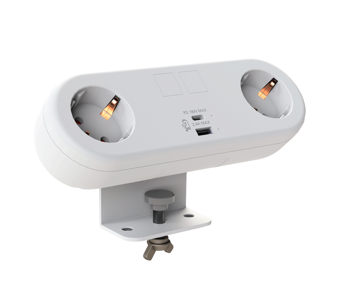
CMD Ltd, the specialist in power and connectivity solutions for commercial environments, has launched a Schuko version of its popular fixed format Capsule workstation power module for export to mainland Europe and beyond. A popular on desk power module comprising two sockets and dual USB (type A and C) chargers, CMD’s Capsule unit is already widely specified in the UK as an off-the-shelf workstation power...

Read more
CMD White Schuko Capsule Desk Power Module
CMD LTD EXTENDS MONITOR ARM RANGE WITH THE LAUNCH OF REACH PLUS

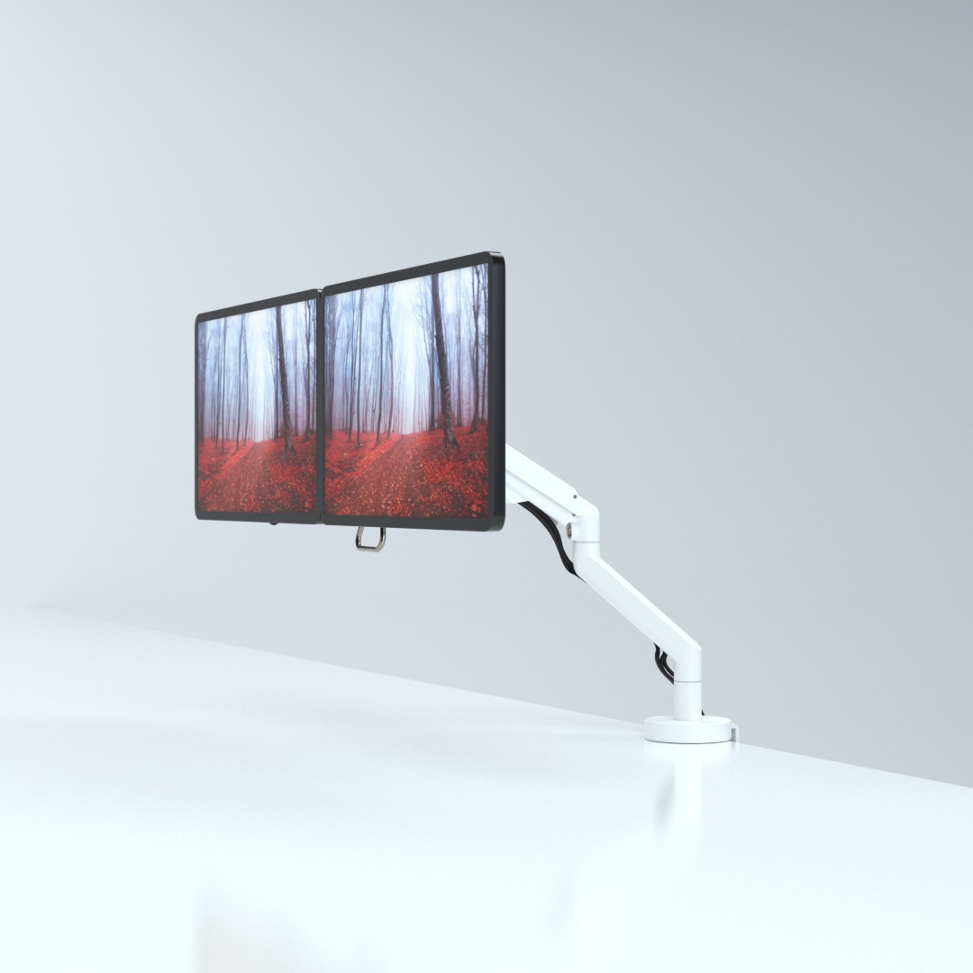
CMD Ltd, the specialist in ergonomic and connectivity solutions for commercial interiors, has completed its Reach monitor arm range with the launch of the Reach Plus. Available in single or dual screen options, the Reach Plus has been designed to provide an ideal solution for both single and dual screen workstation configurations, or can be used with next generation of large format curved screens. Suitable...

Read more
CMD Ltd DEMONSTRATES THE ART OF POWER DISTRIBUTION AT THE UNIVERSITY OF WARWICK

CMD Ltd, the specialist in workplace connectivity and ergonomic solutions, has provided Betatrak busbar power distribution and a range of electrical accessories for two major capital investment projects at the University of Warwick. Designed by Fielden Clegg Bradley Studios, the £33 million Faculty of Arts building is a showpiece development comprising four interconnected structures set around a central atrium, which will enable inter-disciplinary collaboration across...

Read more

University of Warwick
CMD BRINGS HARMONY TO COVENTRY UNIVERSITY RESEARCH FACILITIES

CMD Ltd, the specialist in power distribution solutions and workstation power and ergonomics, has provided under desk and on desk power modules for the refurbishment of three Coventry University research buildings. Located on Coventry University Technology Park, a business park designed to encourage collaboration between the university and knowledge-based businesses, the three buildings are being repurposed as office accommodation for university research teams. The refurbishment...

Read more

Coventry University

Tips for Custom Filter Element Drawing in CAD Software?

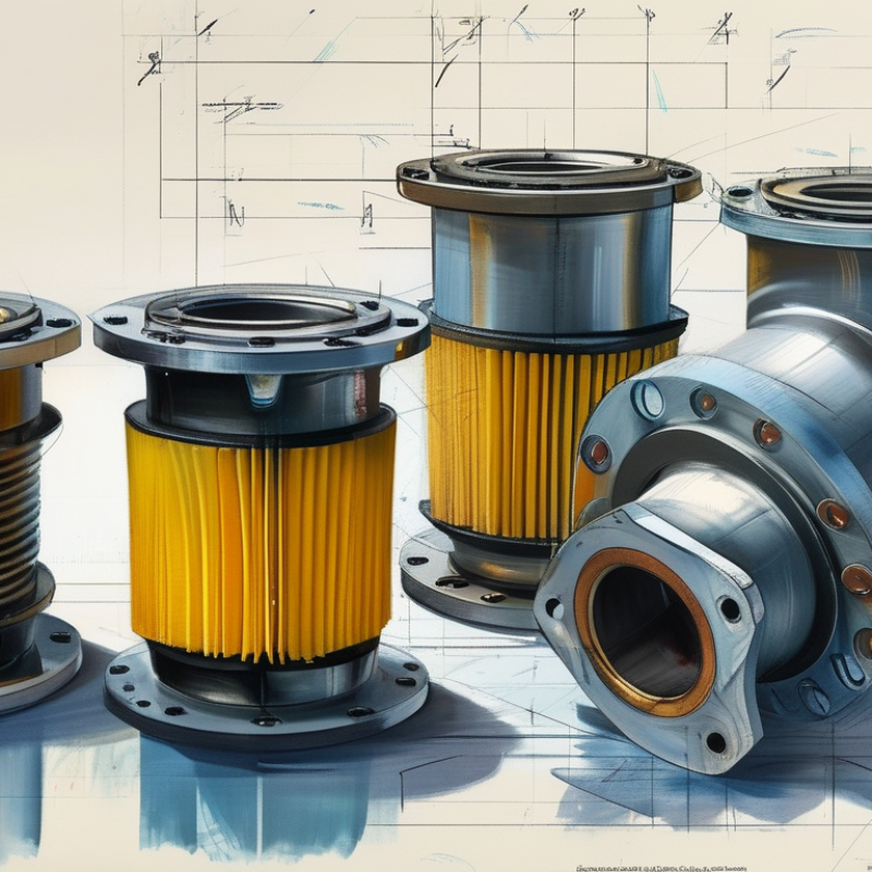
In the world of CAD software, custom filter element drawing CAD is an essential skill. Experts emphasize its importance in creating accurate and efficient designs. John Stevens, an industry leader in CAD applications, states, "Precision in custom filter design can revolutionize performance." His insights highlight a critical aspect of this craft.

Creating custom filter elements in CAD software requires both creativity and technical know-how. The process can be intricate and sometimes frustrating. Each design iteration presents unique challenges, demanding attention to details that could easily be overlooked. A simple miscalculation can lead to significant setbacks.

Aspiring designers should embrace the learning curve. Mistakes are part of the journey. Engaging with advanced tools and techniques is crucial for continuous improvement. The intricacies of custom filter element drawing CAD can shape the future of engineering designs. With dedication and practice, designers can enhance their skills and contribute valuable innovations to the industry.

Tips for Custom Filter Element Drawing in CAD Software?

Understanding Custom Filter Elements in CAD Software

Creating custom filter elements in CAD software can enhance your design workflow. These elements can streamline your project and ensure detailed specifications. To understand these filters, start by identifying the purpose they serve. They aid in isolating components based on specific parameters like size, shape, or material. Recognizing what you need is crucial.

When drawing these elements, precision is key. Use reference points and grid lines for accurate placement. Start with simple shapes before adding complexity. It’s common to overlook minor details during initial drafts. Review your work regularly to catch discrepancies. Seek feedback from colleagues or forums to identify areas for improvement. Engaging with the community often leads to valuable insights.

As you progress, documentation plays a vital role. Keep records of your parameters and decisions. This practice helps in future projects and enhances collaboration. Sometimes, you might find that your initial design needs revisions. Embrace this process; it’s part of growth. Learning from mistakes can lead to better outcomes in your next project. Don’t shy away from experimentation; it’s essential for mastering custom filters.

Tips for Custom Filter Element Drawing in CAD Software

Tip Number Tips Benefits
1 Utilize Layer Management Improves organization and clarity
2 Custom Symbols Creation Saves time in repetitive designs
3 Implementing Blocks for Reusability Enhances design efficiency
4 Use of Styles and Standards Ensures uniformity and compliance
5 Advanced Filtering Options Facilitates targeted element modifications
6 Regularly Update Software Access to new features and bug fixes

Essential Tools for Creating Custom Filter Elements

Creating custom filter elements in CAD software requires a solid understanding of essential tools. Familiarize yourself with drawing tools like lines, arcs, and circles. These basic shapes form the foundation of any custom element. Use layers effectively to organize your work. This helps maintain clarity, especially in complex designs.

For more detailed elements, employ dimensioning tools. They ensure accuracy and scale in your designs. Pay special attention to constraints, as they govern how elements interact. Sometimes, mistakes occur when elements aren’t constrained properly. It can lead to miscommunication during manufacturing. Keep checking and refining your work.

Experiment with materials and textures in your designs. Visual attributes can greatly enhance the presentation. Utilize rendering tools to visualize how your filter elements will look in real life. However, not every design will come out as planned. Mistakes help you learn and improve your design skills. Keep iterating on your ideas to enhance your final products.

Step-by-Step Guide to Drawing Filter Elements in CAD

Creating a custom filter element in CAD software requires attention to detail. Begin by selecting the appropriate workspace. This sets the tone for your drawing. Use gridlines to maintain alignment. Proper alignment ensures your filter element will function as intended. Sketch the basic outline first. It helps visualize the dimensions clearly.

After establishing the outline, add specific features like holes or supports. Pay attention to their placements. Even slight misalignments can impact functionality. Use layer management tools to distinguish between various components. This aids in keeping the drawing organized. Each detail can be critical, especially in filter designs that require precision.

Consider using parametric drawing tools to adjust dimensions easily. It can save time and reduce errors. Be prepared to revise your initial design. Sometimes, ideas don't translate well in CAD. Learning from these adjustments enhances your skills. Use the feedback to refine your technique. Practice consistently, as mastery comes with time and repetition.

Best Practices for Customizing Filter Designs in CAD

Customizing filter designs in CAD software can be a challenging yet rewarding task. Effective customization begins with a clear vision of the filter’s function. Identify the specific requirements, such as size, shape, and material properties. An accurate understanding of the fluid dynamics involved is essential for achieving optimal performance. As you draw, maintain proper layer management and organization, as this will streamline the design process.

Attention to detail is crucial in this phase. Ensure that the dimensions and tolerances meet the specifications precisely. Small errors can lead to significant performance issues later. Regularly reference manufacturer guidelines, as they provide valuable insights. Engaging with forums or communities can also offer perspectives from experienced designers. Sharing ideas and experiences enriches the customization process.

Incorporating iterative feedback loops is beneficial. After completing a design, review it critically. Validate the design against various scenarios to ensure its robustness. This can expose weaknesses in your approach or highlight areas for improvement. Gathering input from peers or mentors can further enhance your design. Open-mindedness during this phase can lead to innovative solutions and prevent costly mistakes.

Common Challenges and Solutions in CAD Filter Drawing

Drawing custom filter elements in CAD software presents several challenges. Common issues include complexity in shapes and ensuring precision in dimensions. Designers often struggle with creating an accurate representation of intricate filter patterns. This can lead to inefficiencies and errors during the manufacturing process.

In drawing filters, attention to detail is crucial. Misalignment or incorrect settings can result in significant redraw efforts. Users should familiarize themselves with the software tools at their disposal. Simple tools can help create complex geometries efficiently. Using layer management effectively can also reduce confusion.

One key strategy is to break down complex shapes into manageable components. This simplification approach makes it easier to work on details. Regular checks against specifications help maintain quality. Sometimes, we overlook small details that can have big impacts. Focusing on these can help improve the overall design process and avoid costly revisits to the drawing board.

Common Challenges in CAD Filter Element Drawing and Their Solutions