

News

Miro: A New Standard in Responsible Innovation

Miro: A New Standard in Responsible Innovation The Miro monitor arm is setting new benchmarks in sustainability. It offers a high-performance solution without compromising on environmental responsibility. Designed with careful material selection, local sourcing, and longevity in mind, Miro’s responsible approach to design and unique manoeuvrability set it apart from the competition. Sustainable Choices Miro is crafted from energy-efficient materials with a lower carbon impact....

Read more
HSE Advisor

Role Purpose Support in the development, implementation and maintenance of the company’s Health, Safety & Environmental policies, processes, operational procedures, and standards.  Ensuring best practice and championing a continually improving HSE culture within the business. Key Responsibilities Liaise with and provide support to all areas of the business to eliminate, mitigate or reduce identified HSE exposures. Partner with the production management team and team leaders,...

Read more
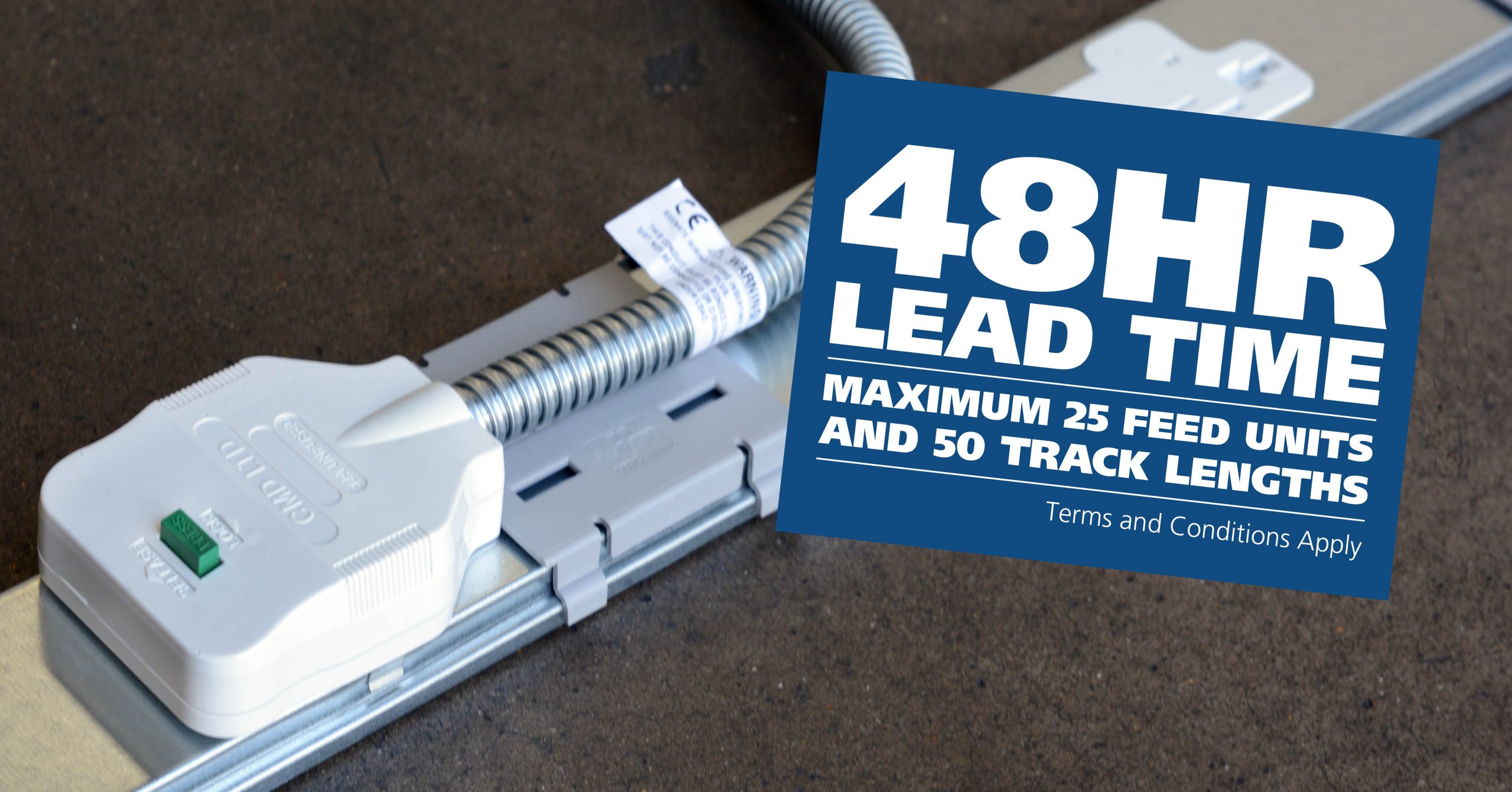
CMD Ltd LAUNCHES 48-HOUR TURNAROUND ON BETATRAK® RAPID ORDERING SERVICE

CMD Ltd, the specialist in power distribution systems, workstation power and monitor arms, has launched a rapid ordering service for its Betatrak® underfloor powertrack distribution systems and accessories, with a commitment to delivering within 48-hours of an approved purchase order*. The service enables customers to order up to 50 lengths of Standard or Clean Earth (C/E) low noise Betatrak, along with up to 25 feed...

Read more
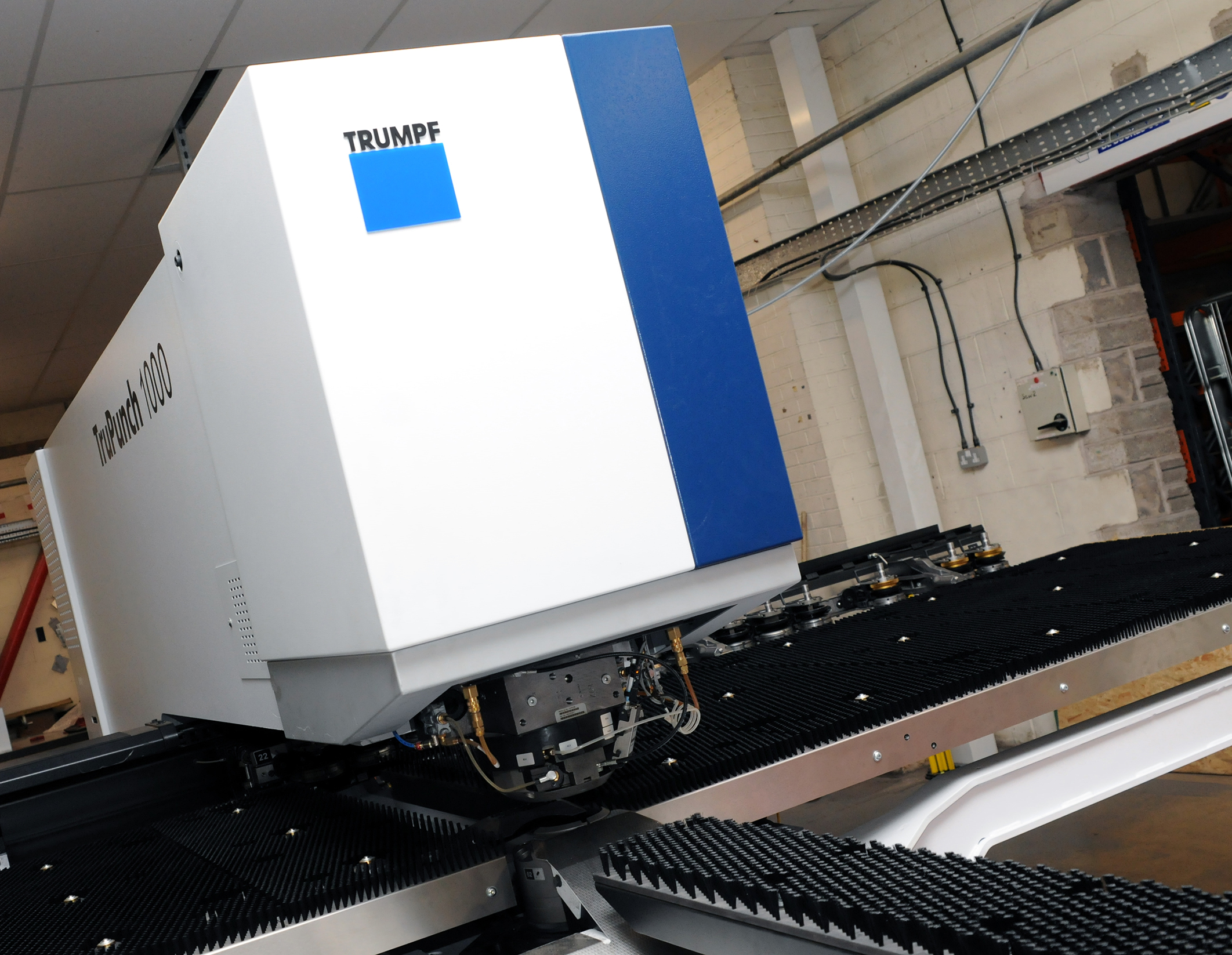
CMD INVESTS £1/4 MILLION IN NEW MACHINE AS PART OF FACTORY UPGRADE

We have invested in a new £1/4m TRUMPF CNC metal punch as part of an asset renewal strategy for our UK manufacturing capability. The new machine will be used in the production of a wide variety of our power distribution systems and workstation power products at our Rotherham factory. Suitable for handling sheet metal between 0.9mm and 3.0mm thick, the new machine will replace one...

Read more
CMD CATALOGUE PROVIDES TECHNICAL POWER DISTRIBUTION GUIDE

CMD Ltd has released a new catalogue, providing an easy to follow technical guide to our power distribution systems and plug and play desk modules. Detailing CMD’s full range of UK-manufactured power distribution systems and plug and play desk modules, the catalogue will be a helpful source of information to M&E engineers and contractors alike to understand how our power distribution systems connect together and...

Read more

Power Distribution Catalogue
CMD Ltd PLAYS ESSENTIAL ROLE IN ELECTRICAL FIT OUT AT LONDON’S PRESTIGIOUS OFFICE DEVELOPMENT

CMD Ltd, specialist in workplace connectivity and ergonomic solutions, has provided a flexible and high-quality power distribution network for The Ray, a prestigious office development in London’s Farringdon. Well-known for being the former site of The Guardian newspaper, The Ray now stands as an 83,000ft² office development characterised by a modernised warehouse aesthetic, with level two now occupied by a global social media company. The...

Read more

The Ray
CMD plugs in to european opportunity with Schuko Capsule unit launch

CMD Ltd, the specialist in power and connectivity solutions for commercial environments, has launched a Schuko version of its popular fixed format Capsule workstation power module for export to mainland Europe and beyond. A popular on desk power module comprising two sockets and dual USB (type A and C) chargers, CMD’s Capsule unit is already widely specified in the UK as an off-the-shelf workstation power...

Read more
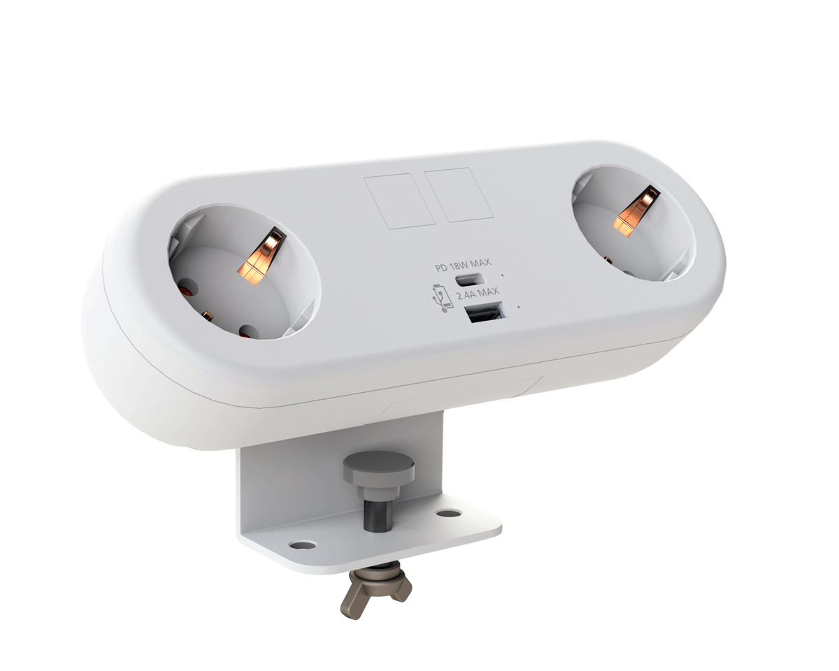
CMD White Schuko Capsule Desk Power Module
CMD LTD EXTENDS MONITOR ARM RANGE WITH THE LAUNCH OF REACH PLUS

CMD Ltd, the specialist in ergonomic and connectivity solutions for commercial interiors, has completed its Reach monitor arm range with the launch of the Reach Plus. Available in single or dual screen options, the Reach Plus has been designed to provide an ideal solution for both single and dual screen workstation configurations, or can be used with next generation of large format curved screens. Suitable...

Read more

CMD Ltd DEMONSTRATES THE ART OF POWER DISTRIBUTION AT THE UNIVERSITY OF WARWICK

CMD Ltd, the specialist in workplace connectivity and ergonomic solutions, has provided Betatrak busbar power distribution and a range of electrical accessories for two major capital investment projects at the University of Warwick. Designed by Fielden Clegg Bradley Studios, the £33 million Faculty of Arts building is a showpiece development comprising four interconnected structures set around a central atrium, which will enable inter-disciplinary collaboration across...

Read more

University of Warwick
CMD BRINGS HARMONY TO COVENTRY UNIVERSITY RESEARCH FACILITIES

CMD Ltd, the specialist in power distribution solutions and workstation power and ergonomics, has provided under desk and on desk power modules for the refurbishment of three Coventry University research buildings. Located on Coventry University Technology Park, a business park designed to encourage collaboration between the university and knowledge-based businesses, the three buildings are being repurposed as office accommodation for university research teams. The refurbishment...

Read more


Coventry University

How to Choose the Right Electronic Pouring Sealants?

Electronic Pouring Sealants help protect circuit boards, sensors, connectors, and power modules from moisture, dust, vibration, and accidental contact. Yet the right material is not simply the hardest or most expensive one. A sealant poured around a compact control board must flow into narrow gaps without trapping air. It must also cure reliably around components that may be sensitive to heat or chemical exposure. Small choices matter. An overly viscous formula can leave hidden voids; a rigid cured layer may stress solder joints during temperature changes. These risks are easy to overlook on a product sheet.

A sound selection starts with real operating conditions: expected temperature range, humidity, vibration, insulation needs, and service life. Compare silicone, polyurethane, and epoxy options by viscosity, cure method, adhesion, hardness, thermal performance, and repairability. Check compatibility with the board, wire insulation, plastics, and metals, rather than relying on a general label such as “electronics grade.” Manufacturer technical data sheets provide useful limits, but they cannot predict every assembly detail. A small trial pour can reveal bubbles, poor wetting, cure inhibition, or difficult rework before production begins. Keep process records. Even careful testing has limits, and one overlooked coating or residue can change the result. This guide explains how to weigh these factors and choose a sealant suited to both the device and the manufacturing process.

How to Choose the Right Electronic Pouring Sealants?

Define Electrical, Thermal, and Chemical Requirements Before Choosing a Sealant

How to Choose the Right Electronic Pouring Sealants?
Define Electrical, Thermal, and Chemical Requirements Before Choosing a Sealant

Before choosing an electronic pouring sealant, define the electrical conditions it must handle. Record working voltage, expected insulation resistance, and whether the assembly faces moisture or electrical noise. Check the sealant’s technical data for dielectric properties and confirm they suit the design. A high rating alone does not guarantee a reliable result. Small details matter.

Thermal demands deserve equal attention. Note the device’s operating temperature, heat spikes, and repeated heating and cooling. A rigid material may stress solder joints or components as temperatures change. Check cure conditions, too, especially if the assembly contains heat-sensitive parts. Chemical compatibility can be less obvious. List nearby plastics, metals, cleaning fluids, oils, and coatings, then confirm the sealant will not damage them. It is easy to overlook a residue from cleaning. Test a representative assembly when possible, since a data sheet cannot reflect every real-world combination.

Tips: Keep a short requirements sheet with voltage, temperature range, and chemical exposures. Pour a small sample around actual components, then inspect for trapped air, poor adhesion, or cure problems. If results look uncertain, pause and review the material choice before production.

How to Choose the Right Electronic Pouring Sealants? - Define Electrical, Thermal, and Chemical Requirements Before Choosing a Sealant
Sealant chemistry Typical dielectric strength Typical thermal conductivity Typical service temperature Electrical considerations Thermal considerations Chemical and environmental resistance Often suitable for Key limitations to check
Epoxy About 15–30 kV/mm About 0.2–0.8 W/(m·K) for unfilled grades; higher for thermally filled grades Often about −40 to 150°C, depending on formulation Generally offers strong insulation and good dimensional stability. Confirm dielectric strength, volume resistivity, and insulation requirements after cure. Rigid formulations can transfer heat effectively when filled, but usually accommodate thermal expansion and vibration less readily than elastomers. Often good resistance to moisture, oils, and many solvents; resistance depends on the specific chemical and exposure conditions. Rigid encapsulation of sensors, transformers, power components, and assemblies needing strong mechanical protection. Can be difficult to remove or rework. Cure exotherm, shrinkage, and stress on delicate components should be evaluated.
Silicone About 15–25 kV/mm About 0.2–0.8 W/(m·K) for common unfilled grades; thermally filled grades can be higher Often about −50 to 200°C, depending on formulation Typically provides good electrical insulation across a wide temperature range. Check dielectric properties at the intended temperature and humidity. Flexible materials can accommodate thermal cycling and vibration. A thermally conductive grade may be needed for heat-sensitive components. Good weathering, ozone, and moisture resistance; compatibility with oils, fuels, and solvents varies by formulation. Assemblies exposed to temperature cycling, vibration, outdoor conditions, or components that need compliant encapsulation. Softness may provide less structural support. Silicone contamination can affect bonding, coating, or other downstream processes.
Polyurethane About 15–25 kV/mm About 0.2–0.6 W/(m·K) for many unfilled grades Often about −40 to 120°C, depending on formulation Can provide good insulation and flexible protection. Verify electrical performance after exposure to moisture and temperature. Its flexibility can reduce stress on components; standard grades are not necessarily high-thermal-conductivity materials. Resistance to water, oils, and chemicals varies considerably. Some formulations can be sensitive to moisture during processing or long-term exposure. Encapsulation where flexibility, impact protection, and moderate operating temperatures are important. Check humidity sensitivity during mixing and cure, hydrolysis resistance, and compatibility with the actual fluids or cleaning agents.
Thermally conductive silicone Often about 10–20 kV/mm; confirm the grade and test method Commonly about 0.8–3 W/(m·K), with specialty grades available outside this range Often about −40 to 180°C, depending on formulation Thermal fillers can change electrical properties. Confirm that the selected grade is electrically insulating if that is required. Designed to improve heat transfer while retaining silicone flexibility. Compare conductivity alongside viscosity and cured hardness. Generally retains silicone-like weathering and moisture performance, but chemical compatibility remains formulation-specific. Power electronics, LED assemblies, and components where heat transfer and thermal-cycle compliance are both priorities. Higher filler loading can affect flow, dispensing, and component wetting. Thermal conductivity alone does not guarantee a low-resistance heat path.
Acrylic About 10–25 kV/mm, depending on formulation and cure About 0.15–0.4 W/(m·K) for many unfilled grades Often about −40 to 120°C, depending on formulation Electrical properties and cure depth should be validated for the actual part geometry and light exposure, where UV curing is used. Usually selected for rapid curing or rework considerations rather than high heat transfer. Resistance to moisture and chemicals varies by chemistry; test against the specific cleaner, solvent, or process fluid. Small assemblies and applications where fast cure or easier inspection and repair are useful. Shadowed areas may not cure fully in light-cured systems. Confirm cure method, depth, and compatibility with plastics.
Selection note: Values shown are indicative ranges for common material families, not guaranteed specifications. Actual properties vary by formulation, filler loading, cure schedule, specimen thickness, and test method. Before selection, define the required dielectric performance, operating and peak temperatures, heat-flow path, chemical exposure, moisture level, component sensitivity, and rework needs; then verify the supplier’s current technical data and test the material in the finished assembly.

Compare Dielectric Strength Under ASTM D149 and Resistivity Under ASTM D257

Electronic pouring sealants protect coils, sensors, and circuit assemblies, but one electrical number cannot describe their insulation performance. ASTM D149 measures dielectric breakdown strength: the voltage at which a specimen fails, often reported in kilovolts per millimetre. ASTM D257 measures insulation resistance and calculates resistivity, commonly reported in ohm-centimetres. These are different properties, not competing versions of the same test.

Compare actual laboratory reports, not just catalogue figures. Under ASTM D149, check specimen thickness, electrode setup, voltage type, temperature, and conditioning. A thin, dry coupon may perform differently from a thick casting with trapped moisture. Under ASTM D257, review the applied voltage, electrification time, humidity, and whether the result is volume or surface resistivity. The ASTM methods define test procedures; they do not set one universal pass value for every sealant. Small details matter.

For a high-voltage assembly, D149 results help assess resistance to sudden electrical breakdown. D257 results help evaluate leakage through or across the cured material during service. Read both sets of figures together, and request the underlying test report when conditions are unclear. I would still question a very high resistivity figure if the report omits humidity or conditioning. It may look reassuring, but the test context is part of the data. Sources: ASTM D149 and ASTM D257.

Match Thermal Conductivity and Operating Range to Component Heat Loads

How to Choose the Right Electronic Pouring Sealants?

Match thermal conductivity and operating range to the component’s actual heat load. A sealant around a warm sensor faces different demands from one enclosing a power module beside a hot heat sink. Check the component’s steady-state temperature, peak excursions, and heat path before comparing products. NIST reference data puts bulk copper near 400 W/m·K and aluminum near 237 W/m·K at room temperature. These are useful scale markers, not realistic targets for filled sealants. That gap matters.

Ask for thermal conductivity measured by ASTM D5470, and compare values only when test methods and sample conditions match. A higher figure can help move heat toward an enclosure, but it cannot compensate for a thick pour, trapped air, or poor contact. Inspect the cured section for voids. Then confirm the sealant’s continuous operating range covers the measured component temperature, including brief peaks and cold starts. IEC 60216 describes methods for assessing thermal endurance; its approach reinforces why a temperature rating should be tied to aging evidence, not a single short test. A real trade-off.

In practice, a thin layer over a warm metal case may need less conductivity than a deep encapsulation around a concentrated hotspot. Review cure shrinkage and heat-cycle performance, too. They are easy to overlook. If data sheets omit test details or aging conditions, ask for them before choosing. A neat conductivity number alone is not enough.

Check UL 94 V-0 Limits: ≤10 s Afterflame per Application, ≤50 s Total

How to Choose the Right Electronic Pouring Sealants?

When selecting an electronic pouring sealant, check the UL 94 V-0 test results, not just the product description. Under the specified test conditions, afterflame must not exceed 10 seconds after either flame application. The total afterflame time across the test’s applications must stay at or below 50 seconds. Ask for the test report and confirm it covers the exact material grade and relevant thickness. A rating alone is not a field-use guarantee.

Then consider how the sealant behaves in your assembly. Compare the tested thickness with the depth used around wires, connectors, and components. Review cure conditions, adhesion, and compatibility with the substrate; a thin test sample may not represent a deep pour. I would also check how the cured material performs after heat exposure. This step is easy to overlook, and it can complicate an otherwise sound choice.

Tips: Check the report’s specimen thickness and flame-time records. Match them to your design. If they do not match, ask for clarification before approving the material.

Validate Cure, Adhesion, and Temperature Cycling on Representative Assemblies

How to Choose the Right Electronic Pouring Sealants?

Validate Cure, Adhesion, and Temperature Cycling on Representative Assemblies

A sealant that cures well in a small cup may behave differently inside a packed enclosure. Test it on assemblies that match your real design, including connectors, wire insulation, coatings, and tight corners. Record the mix ratio, dispense time, ambient temperature, and cure duration. Then inspect the material through its full depth for soft spots, bubbles, or tackiness. Small details matter.

Adhesion should be checked on the actual substrate, not only on a clean test coupon. Surface oils, coating variations, and handling can change the bond. After cure, expose assemblies to the temperature range and cycle pattern expected in service. Look for cracks, edge lift, void growth, or sealant pulling away from wires. Check electrical performance too, where relevant. A result that looks sound can still be imperfect; note any inconsistent samples rather than averaging them away.