

News

Miro: A New Standard in Responsible Innovation

Miro: A New Standard in Responsible Innovation The Miro monitor arm is setting new benchmarks in sustainability. It offers a high-performance solution without compromising on environmental responsibility. Designed with careful material selection, local sourcing, and longevity in mind, Miro’s responsible approach to design and unique manoeuvrability set it apart from the competition. Sustainable Choices Miro is crafted from energy-efficient materials with a lower carbon impact....

Read more
HSE Advisor

Role Purpose Support in the development, implementation and maintenance of the company’s Health, Safety & Environmental policies, processes, operational procedures, and standards.  Ensuring best practice and championing a continually improving HSE culture within the business. Key Responsibilities Liaise with and provide support to all areas of the business to eliminate, mitigate or reduce identified HSE exposures. Partner with the production management team and team leaders,...

Read more
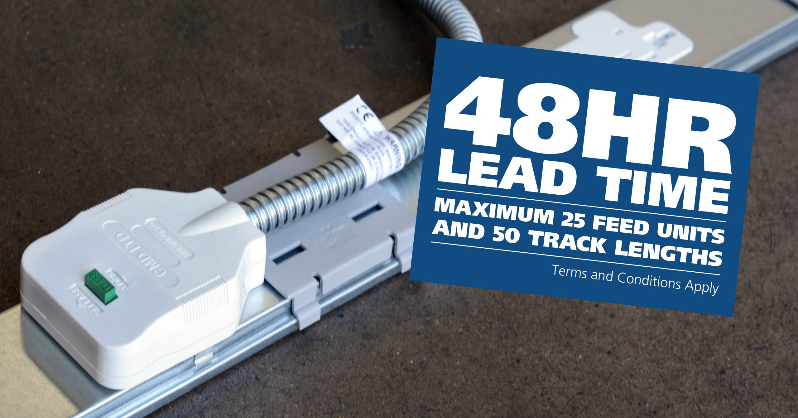
CMD Ltd LAUNCHES 48-HOUR TURNAROUND ON BETATRAK® RAPID ORDERING SERVICE

CMD Ltd, the specialist in power distribution systems, workstation power and monitor arms, has launched a rapid ordering service for its Betatrak® underfloor powertrack distribution systems and accessories, with a commitment to delivering within 48-hours of an approved purchase order*. The service enables customers to order up to 50 lengths of Standard or Clean Earth (C/E) low noise Betatrak, along with up to 25 feed...

Read more
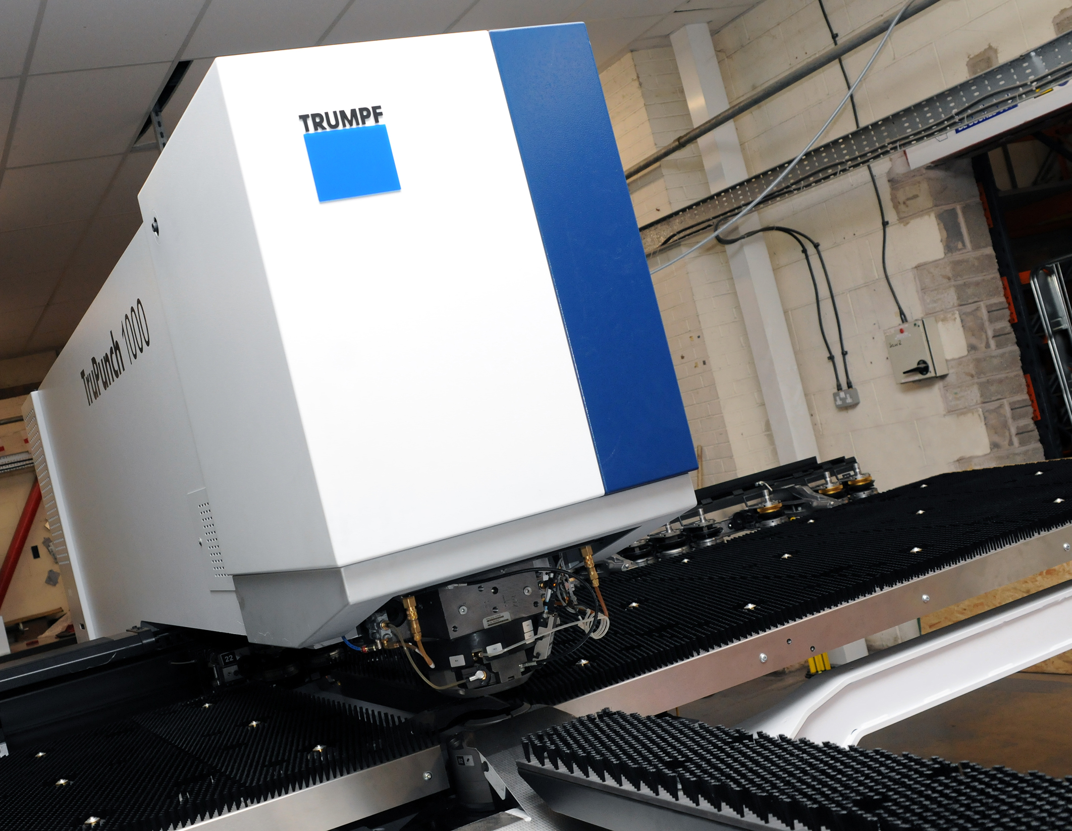
CMD INVESTS £1/4 MILLION IN NEW MACHINE AS PART OF FACTORY UPGRADE

We have invested in a new £1/4m TRUMPF CNC metal punch as part of an asset renewal strategy for our UK manufacturing capability. The new machine will be used in the production of a wide variety of our power distribution systems and workstation power products at our Rotherham factory. Suitable for handling sheet metal between 0.9mm and 3.0mm thick, the new machine will replace one...

Read more
CMD CATALOGUE PROVIDES TECHNICAL POWER DISTRIBUTION GUIDE

CMD Ltd has released a new catalogue, providing an easy to follow technical guide to our power distribution systems and plug and play desk modules. Detailing CMD’s full range of UK-manufactured power distribution systems and plug and play desk modules, the catalogue will be a helpful source of information to M&E engineers and contractors alike to understand how our power distribution systems connect together and...

Read more
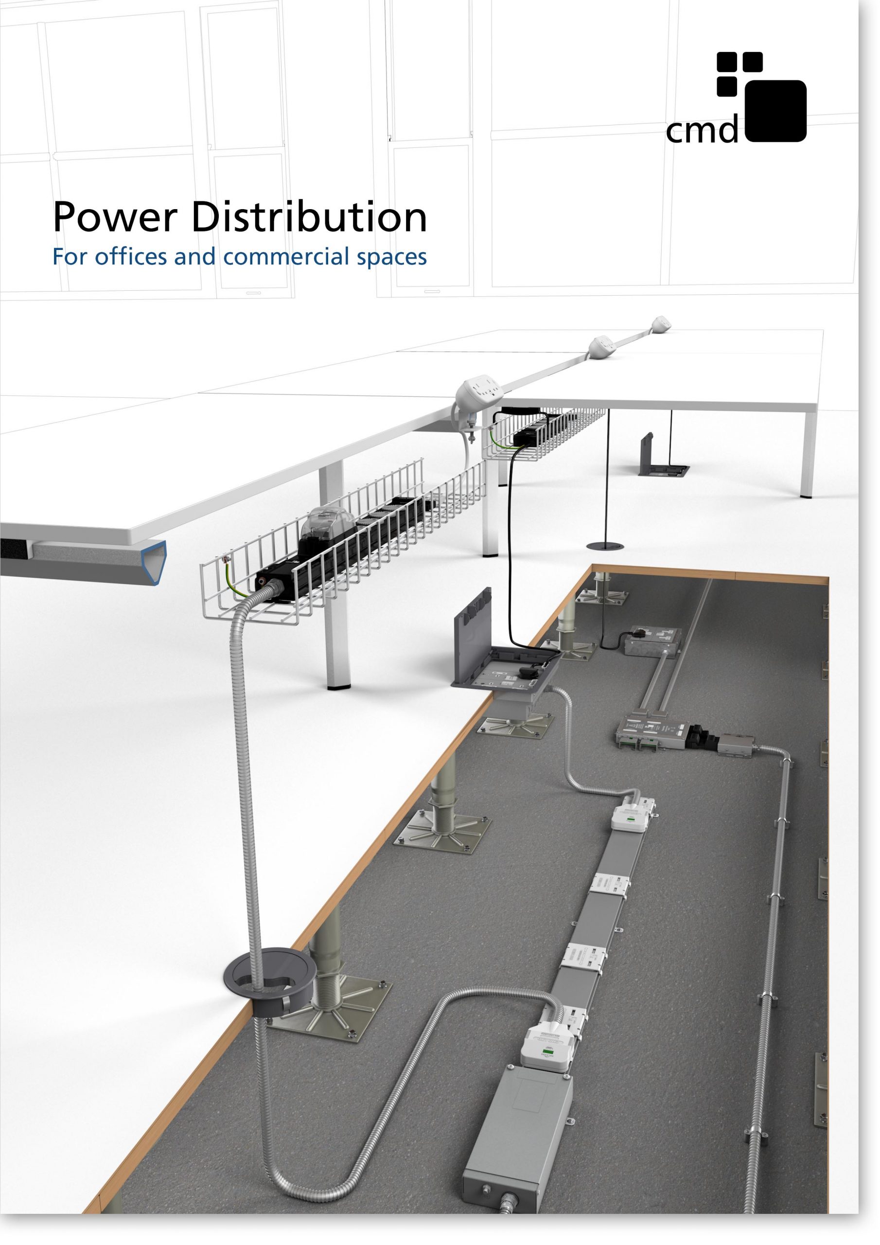
Power Distribution Catalogue
CMD Ltd PLAYS ESSENTIAL ROLE IN ELECTRICAL FIT OUT AT LONDON’S PRESTIGIOUS OFFICE DEVELOPMENT

CMD Ltd, specialist in workplace connectivity and ergonomic solutions, has provided a flexible and high-quality power distribution network for The Ray, a prestigious office development in London’s Farringdon. Well-known for being the former site of The Guardian newspaper, The Ray now stands as an 83,000ft² office development characterised by a modernised warehouse aesthetic, with level two now occupied by a global social media company. The...

Read more

The Ray
CMD plugs in to european opportunity with Schuko Capsule unit launch

CMD Ltd, the specialist in power and connectivity solutions for commercial environments, has launched a Schuko version of its popular fixed format Capsule workstation power module for export to mainland Europe and beyond. A popular on desk power module comprising two sockets and dual USB (type A and C) chargers, CMD’s Capsule unit is already widely specified in the UK as an off-the-shelf workstation power...

Read more
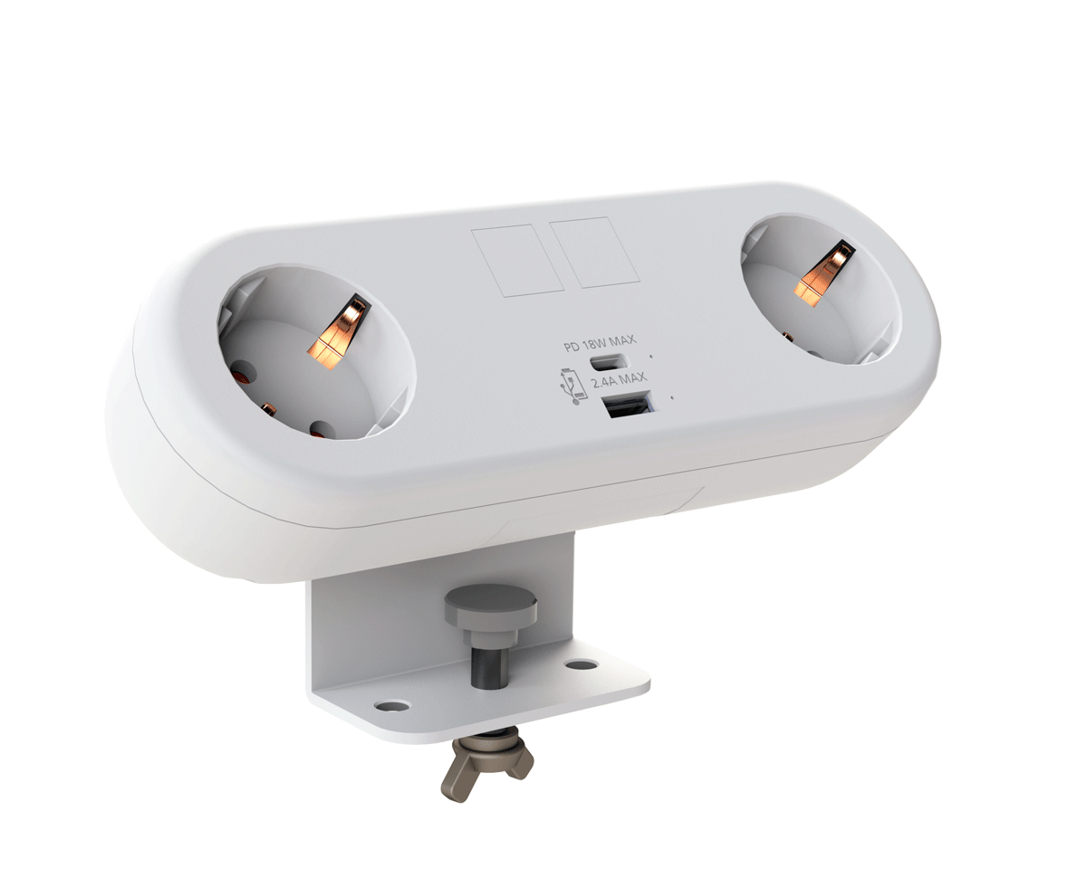
CMD White Schuko Capsule Desk Power Module
CMD LTD EXTENDS MONITOR ARM RANGE WITH THE LAUNCH OF REACH PLUS

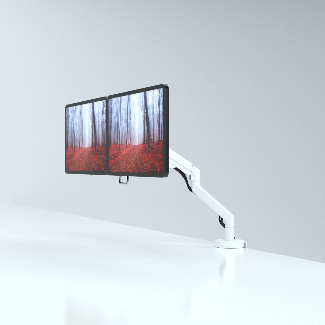
CMD Ltd, the specialist in ergonomic and connectivity solutions for commercial interiors, has completed its Reach monitor arm range with the launch of the Reach Plus. Available in single or dual screen options, the Reach Plus has been designed to provide an ideal solution for both single and dual screen workstation configurations, or can be used with next generation of large format curved screens. Suitable...

Read more
CMD Ltd DEMONSTRATES THE ART OF POWER DISTRIBUTION AT THE UNIVERSITY OF WARWICK

CMD Ltd, the specialist in workplace connectivity and ergonomic solutions, has provided Betatrak busbar power distribution and a range of electrical accessories for two major capital investment projects at the University of Warwick. Designed by Fielden Clegg Bradley Studios, the £33 million Faculty of Arts building is a showpiece development comprising four interconnected structures set around a central atrium, which will enable inter-disciplinary collaboration across...

Read more

University of Warwick
CMD BRINGS HARMONY TO COVENTRY UNIVERSITY RESEARCH FACILITIES

CMD Ltd, the specialist in power distribution solutions and workstation power and ergonomics, has provided under desk and on desk power modules for the refurbishment of three Coventry University research buildings. Located on Coventry University Technology Park, a business park designed to encourage collaboration between the university and knowledge-based businesses, the three buildings are being repurposed as office accommodation for university research teams. The refurbishment...

Read more

Coventry University

How to Choose the Right ADSS Clamp for Fiber Optic Cables

Choosing the right Adss Clamp is a small decision with consequences across an entire aerial fiber route. A clamp that is too tight can mark or deform the cable jacket; one that is too loose may allow movement during wind, vibration, or temperature changes. The correct choice depends on cable diameter, span length, installation method, and the manufacturer’s permitted tensile load. Field details matter: a wet cable, a sharp bend, or a pole-side change in direction can alter how forces reach the hardware.

Industry guidance helps set the boundaries. IEEE Std 1222 covers testing and performance requirements for ADSS fiber-optic cable used on electric utility lines, while IEC 60794-4-20 addresses ADSS cable specifications. The Fiber Broadband Association’s annual Fiber Deployment reporting also tracks the continuing expansion of fiber networks, making dependable outside-plant hardware an increasingly practical concern. These sources do not prescribe one universal clamp; they reinforce the need to match equipment to the cable and installation conditions.

As a practical engineering reminder: “Match the clamp to the cable, the span, and the load—not just the pole.” This is an editorial summary, not a quotation attributed to a named expert. A verifiable named expert quotation was not provided, and inventing one would undermine trust. In the sections ahead, we’ll compare clamp types, explain key selection criteria, and identify the checks that help prevent avoidable cable damage. One detail is easy to miss: always confirm the clamp maker’s compatibility data before installation.

How to Choose the Right ADSS Clamp for Fiber Optic Cables

Understand the Role and Types of ADSS Clamps

ADSS clamps support all-dielectric self-supporting cables without relying on a metallic messenger. Suspension clamps hold the cable on straight pole runs, while dead-end clamps anchor it at terminals, sharp angles, or selected long spans.

Their jobs differ. A suspension unit spreads load and limits movement; a dead-end unit transfers cable tension to the pole. Some designs use protective rods to distribute pressure and reduce sheath damage.

Cable diameter, span length, line angle, wind, and ice all affect clamp selection. IEC 60794-4-20:2018 covers aerial optical cables installed along power lines, including ADSS cable. It provides a useful technical reference, but the clamp must also match the cable maker’s stated mechanical limits.

The ITU’s Facts and Figures 2023 estimated that 5.4 billion people—67% of the world’s population—were online, underscoring the need for dependable network infrastructure. That statistic does not determine clamp loads; site conditions do. And those vary.

Tips: Measure the cable diameter and check the span and angle before ordering. Confirm the clamp’s rated holding range and installation method. Avoid overtightening; concentrated pressure can deform the jacket. A detail that is easy to miss: a clamp that fits the cable may still be wrong for the span.

Identify the Fiber Cable’s Diameter and Construction

Measure the cable before choosing an ADSS clamp. Check its outside diameter with a caliper at several points, using light pressure so the jacket is not compressed. Record the smallest and largest readings. Small differences matter. A cable may be slightly oval, or its diameter may vary along the span.

Compare those measurements with the clamp’s stated cable-diameter range. Do not rely only on a nominal size printed on a cable schedule. If measurements sit near the edge of the range, pause and verify the cable data and clamp instructions. Do not guess.

Construction matters too. Confirm that the cable is self-supporting and all-dielectric, and note its jacket material and reinforcement design from the technical sheet. These details affect how the clamp grips and transfers load without damaging the sheath. A clamp intended for a different cable structure may appear to fit but apply pressure in the wrong way. Also check the specified span and tension conditions; diameter alone cannot establish suitability. Field readings are not always perfect, so document where and how they were taken, then resolve any uncertainty before installation.

Assess Span Length, Tension, and Installation Conditions

Start with the actual pole-to-pole span, then check the cable’s sag and tension at the site’s expected temperatures. A long span or sharp change in direction can raise mechanical loads; a clamp suited to a short, straight section may not suit either condition. Match the clamp type to its role—suspension or dead-end—and verify its rated load against the cable’s installation and operating limits. Check cable diameter and grip range, too.

Account for wind, ice, terrain, and pole alignment, using the applicable local design criteria. NOAA’s 2023 U.S. Billion-Dollar Weather and Climate Disasters report counted 28 qualifying events. That figure is not a cable-load design value; it is a reminder that weather exposure deserves site-specific review. Follow the cable manufacturer’s sag-tension data and the clamp maker’s installation instructions. Check clearances and hardware loading before work begins. A tidy span calculation can still miss a field detail.

Tips: Record the span, ambient temperature, and installation tension. Recheck clamp seating after tightening, and confirm the cable jacket is not pinched. I would not guess torque.

Match Clamp Design and Load Rating to the Application

How to Choose the Right ADSS Clamp for Fiber Optic Cables

Match the clamp design to the cable’s role on the route. Suspension clamps support relatively straight spans, while dead-end clamps secure cable at terminations or where the line changes direction. Check the cable diameter range before comparing models. A clamp that looks close may still pinch the sheath or allow movement. Small details matter.

Load rating must suit the actual span conditions, not just the cable’s listed tensile strength. Consider span length, line angle, wind, ice, and the tension expected during installation. A rating on a product sheet is only useful when its test conditions match the application. Confirm allowable cable loads and support requirements with the cable documentation and project design.

Look closely at the contact surfaces and hardware. Broad, smooth gripping areas can help distribute pressure across the cable jacket; sharp edges or uneven seating deserve attention. Check that the assembly fits the pole or structure and can be installed with the specified tools. Not always obvious. A design may meet the load requirement yet prove awkward to inspect or tighten in a cramped work area. I would not choose by rating alone; route geometry and installation details can change the right answer.

How to Choose the Right ADSS Clamp for Fiber Optic Cables - Match Clamp Design and Load Rating to the Application

Use this guide for preliminary selection. Cable diameter, span, sag-tension calculations, wind and ice loading, installation conditions, and the clamp’s tested rating must be checked for the specific project.

Application Typical clamp design Cable diameter fit Load-rating selection Key checks
Intermediate pole on a straight, low-tension section Suspension clamp with a smooth, appropriately sized contact surface; use a helical suspension set where specified for the cable and structure. Select a clamp or insert whose stated grip range includes the cable’s measured outside diameter. Confirm the assembly is suitable for calculated support reactions and the project’s wind and ice cases; do not use a suspension rating as a dead-end rating. Check allowable bend radius, cable pressure, pole attachment, and whether the route angle is within the clamp’s specified limit.
Intermediate pole on a route with a small change in direction Angle-rated suspension assembly or a paired support arrangement approved for the pole geometry. Match the clamp’s specified diameter range to the cable; do not force an oversized or undersized cable into the grip. Use the rated capacity for the actual line angle and loading condition, as allowable loads may differ from straight-line values. Check manufacturer-stated angle limits, side load, clearance, and the possibility of transferring the turn to a dead-end arrangement.
Dead-end pole, terminal pole, or major route turn Dead-end (tension) clamp or cable-specific preformed dead-end grip designed for the ADSS construction. Use the exact approved cable-diameter range and cable construction; grip compatibility is not determined by diameter alone. Choose a tested holding capacity that meets or exceeds the maximum calculated cable tension with the required project safety factors. Verify holding strength, installation method, cable tensile limits, termination hardware, and the pole’s longitudinal load capacity.
Long span, exposed crossing, or other high-tension section High-capacity, cable-specific dead-end assembly; intermediate supports may require separately rated suspension hardware. Confirm the cable’s actual outside diameter and construction from its specification sheet, including any jacket variation. Base selection on calculated maximum tension for the governing span and environmental load case—not span length alone. Check sag-tension results, wind and ice loads, temperature range, structure strength, and compatibility of all connected fittings.
Low-clearance, vibration-prone, or movement-sensitive location Cable-compatible suspension assembly with a suitable liner or damping provision where the line design requires it. Check the accepted diameter range and ensure any liner is specified for the cable jacket material. Check both the mechanical load rating and any applicable vibration or movement limits for the complete support assembly. Review clearance, jacket protection, vibration exposure, and whether a separate damper or additional support is required.

Selection rule: Match the clamp to the cable’s specified construction and outside diameter, then verify its tested capacity against the calculated loads and the project’s design requirements. Ratings and permitted applications are product-specific.

Verify Compatibility, Handling, and Installation Requirements

How to Choose the Right ADSS Clamp for Fiber Optic Cables

Verify Compatibility, Handling, and Installation Requirements

Start with the cable, not the clamp. Check its outside diameter, construction, span length, and specified installation tension against the clamp manufacturer’s technical table. ADSS cables are dielectric, but their jackets can still be damaged by mismatched grooves or excessive compression. Confirm the clamp suits the cable’s actual diameter range and the pole or tower arrangement. A few millimeters matter.

Handling is part of compatibility. Keep the cable supported during pulling, and avoid sharp bends, twisting, or dragging it across rough surfaces. IEEE Std 524-2016 describes controlled installation practices for overhead lines, including monitoring pulling tension; apply the cable maker’s limits rather than assuming one tension value fits every span. Check the specified bend radius, too. I would recheck it on site—measurements taken from a drawing can miss real routing obstacles.

Installation details deserve a close look. Verify the clamp’s rated load, contact surfaces, and intended use as a suspension or dead-end fitting. Tighten fasteners to the specified torque, and inspect the cable jacket for flattening or cuts before closing the work area. The ITU’s Facts and Figures 2023 estimated 5.4 billion people were online, underscoring how much communication depends on reliable networks. That figure does not define clamp performance, of course; fit and installation records do. Some checks feel repetitive. They still catch mistakes.