

News

Miro: A New Standard in Responsible Innovation

Miro: A New Standard in Responsible Innovation The Miro monitor arm is setting new benchmarks in sustainability. It offers a high-performance solution without compromising on environmental responsibility. Designed with careful material selection, local sourcing, and longevity in mind, Miro’s responsible approach to design and unique manoeuvrability set it apart from the competition. Sustainable Choices Miro is crafted from energy-efficient materials with a lower carbon impact....

Read more
HSE Advisor

Role Purpose Support in the development, implementation and maintenance of the company’s Health, Safety & Environmental policies, processes, operational procedures, and standards.  Ensuring best practice and championing a continually improving HSE culture within the business. Key Responsibilities Liaise with and provide support to all areas of the business to eliminate, mitigate or reduce identified HSE exposures. Partner with the production management team and team leaders,...

Read more
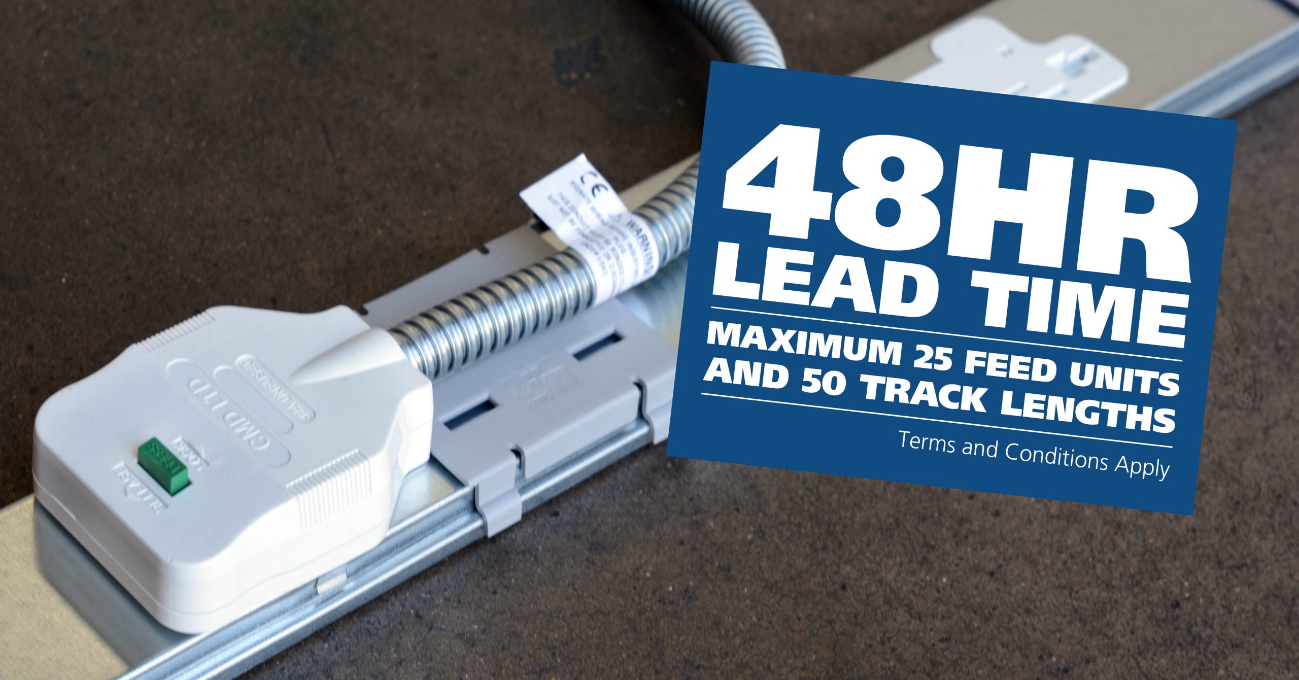
CMD Ltd LAUNCHES 48-HOUR TURNAROUND ON BETATRAK® RAPID ORDERING SERVICE

CMD Ltd, the specialist in power distribution systems, workstation power and monitor arms, has launched a rapid ordering service for its Betatrak® underfloor powertrack distribution systems and accessories, with a commitment to delivering within 48-hours of an approved purchase order*. The service enables customers to order up to 50 lengths of Standard or Clean Earth (C/E) low noise Betatrak, along with up to 25 feed...

Read more
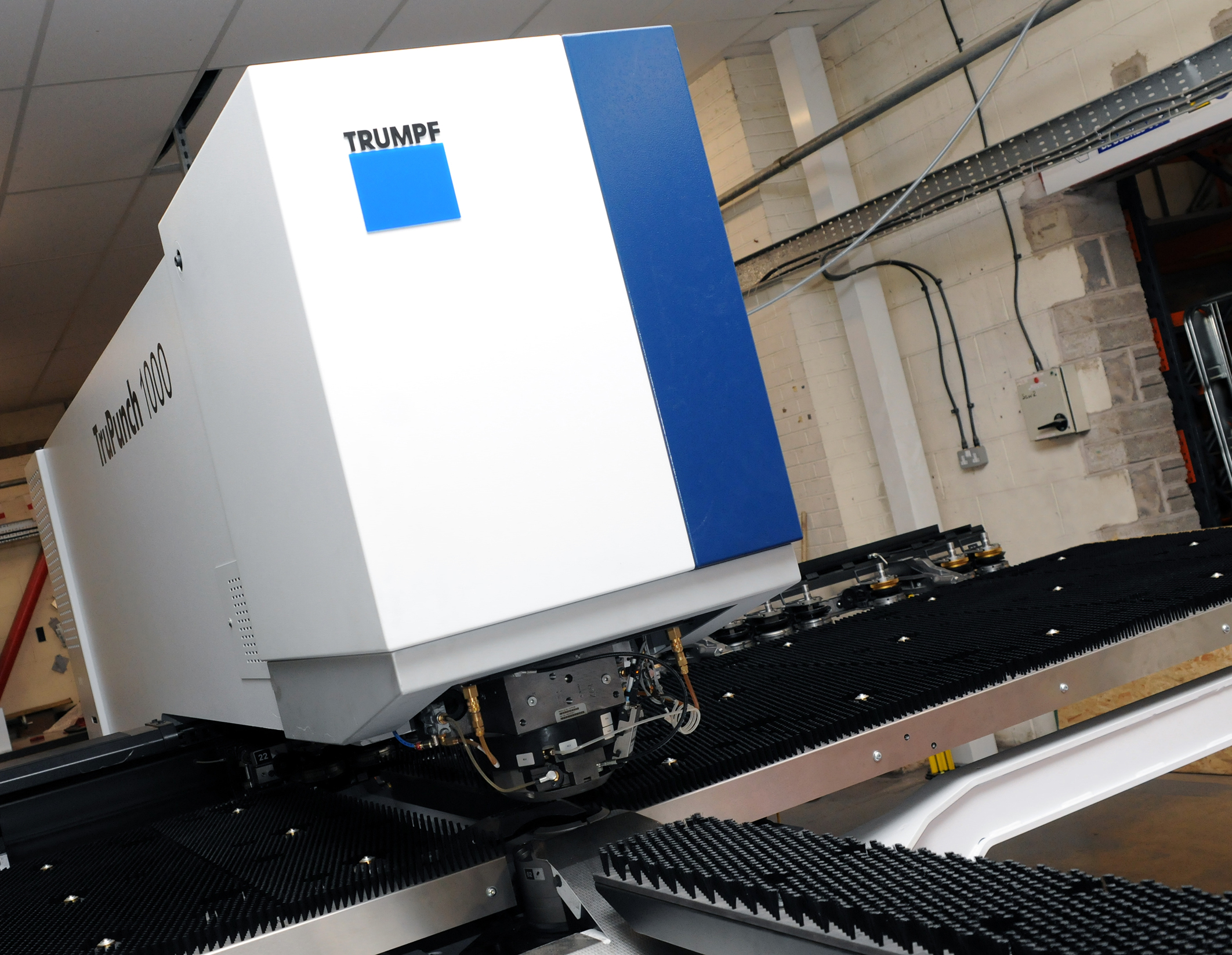
CMD INVESTS £1/4 MILLION IN NEW MACHINE AS PART OF FACTORY UPGRADE

We have invested in a new £1/4m TRUMPF CNC metal punch as part of an asset renewal strategy for our UK manufacturing capability. The new machine will be used in the production of a wide variety of our power distribution systems and workstation power products at our Rotherham factory. Suitable for handling sheet metal between 0.9mm and 3.0mm thick, the new machine will replace one...

Read more
CMD CATALOGUE PROVIDES TECHNICAL POWER DISTRIBUTION GUIDE

CMD Ltd has released a new catalogue, providing an easy to follow technical guide to our power distribution systems and plug and play desk modules. Detailing CMD’s full range of UK-manufactured power distribution systems and plug and play desk modules, the catalogue will be a helpful source of information to M&E engineers and contractors alike to understand how our power distribution systems connect together and...

Read more
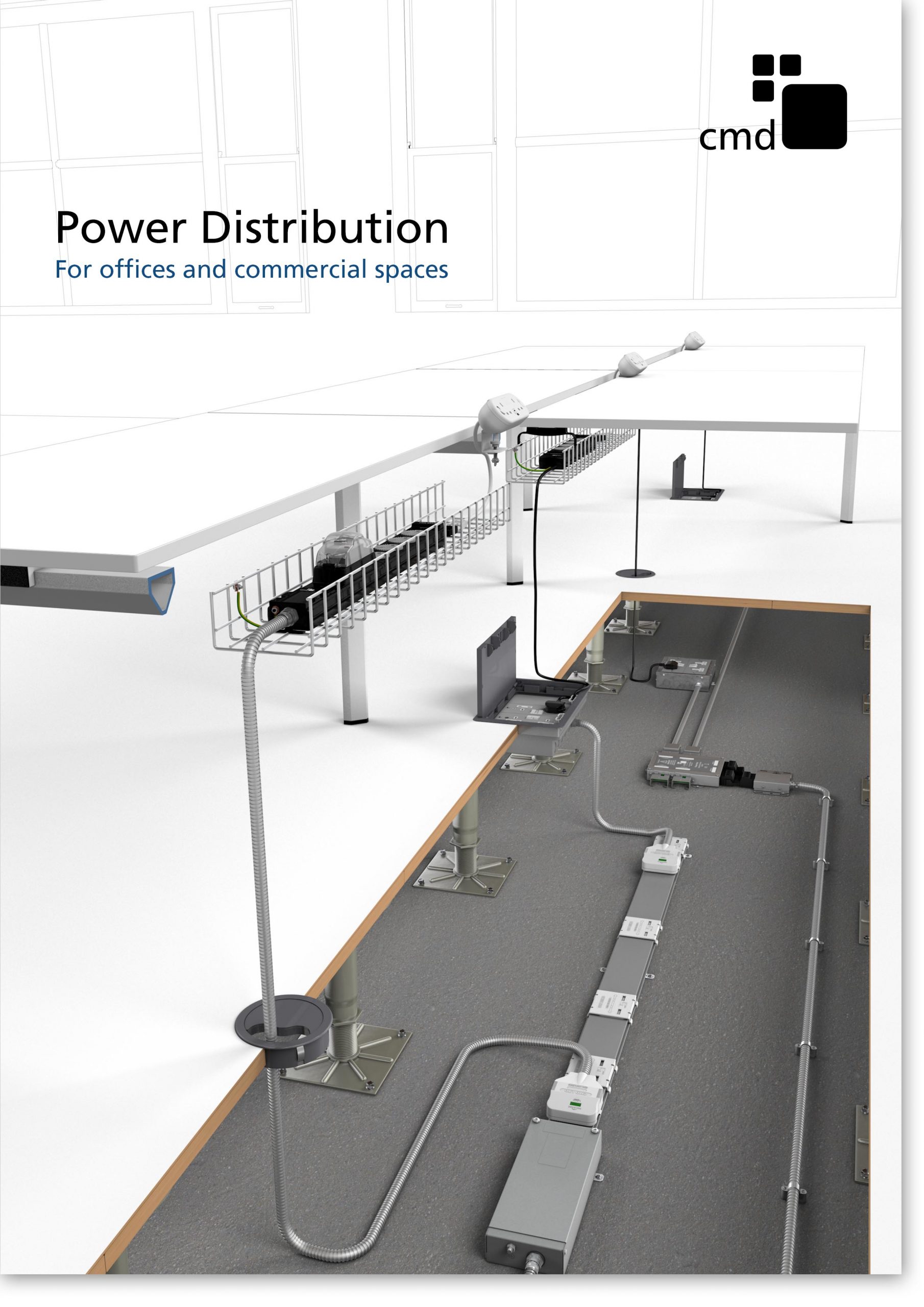
Power Distribution Catalogue
CMD Ltd PLAYS ESSENTIAL ROLE IN ELECTRICAL FIT OUT AT LONDON’S PRESTIGIOUS OFFICE DEVELOPMENT

CMD Ltd, specialist in workplace connectivity and ergonomic solutions, has provided a flexible and high-quality power distribution network for The Ray, a prestigious office development in London’s Farringdon. Well-known for being the former site of The Guardian newspaper, The Ray now stands as an 83,000ft² office development characterised by a modernised warehouse aesthetic, with level two now occupied by a global social media company. The...

Read more

The Ray
CMD plugs in to european opportunity with Schuko Capsule unit launch

CMD Ltd, the specialist in power and connectivity solutions for commercial environments, has launched a Schuko version of its popular fixed format Capsule workstation power module for export to mainland Europe and beyond. A popular on desk power module comprising two sockets and dual USB (type A and C) chargers, CMD’s Capsule unit is already widely specified in the UK as an off-the-shelf workstation power...

Read more
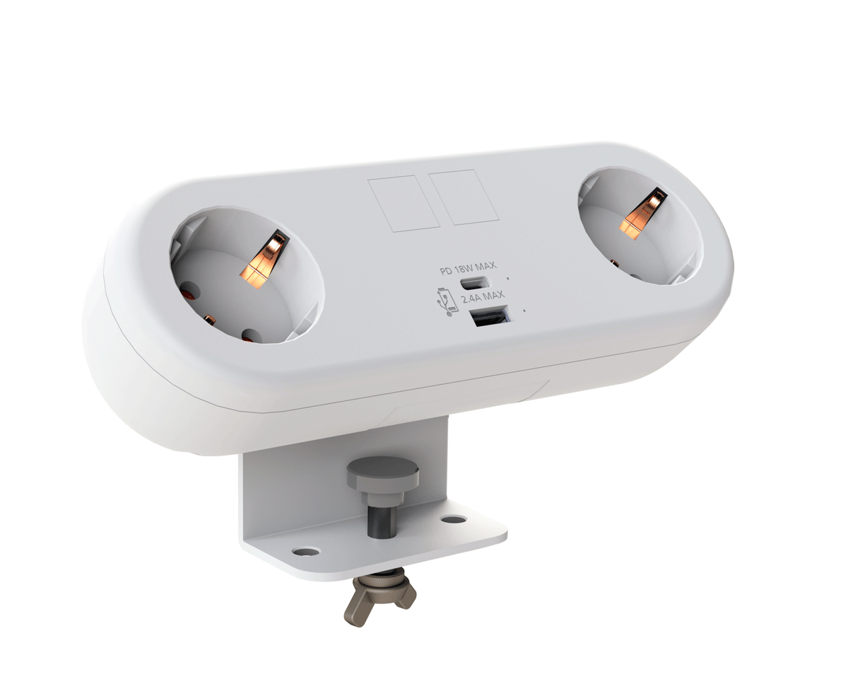
CMD White Schuko Capsule Desk Power Module
CMD LTD EXTENDS MONITOR ARM RANGE WITH THE LAUNCH OF REACH PLUS

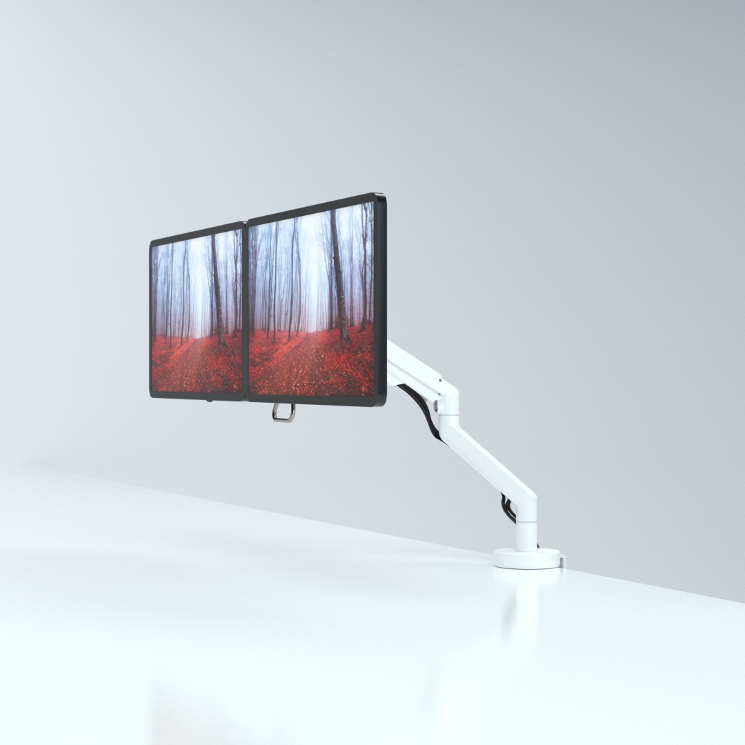
CMD Ltd, the specialist in ergonomic and connectivity solutions for commercial interiors, has completed its Reach monitor arm range with the launch of the Reach Plus. Available in single or dual screen options, the Reach Plus has been designed to provide an ideal solution for both single and dual screen workstation configurations, or can be used with next generation of large format curved screens. Suitable...

Read more
CMD Ltd DEMONSTRATES THE ART OF POWER DISTRIBUTION AT THE UNIVERSITY OF WARWICK

CMD Ltd, the specialist in workplace connectivity and ergonomic solutions, has provided Betatrak busbar power distribution and a range of electrical accessories for two major capital investment projects at the University of Warwick. Designed by Fielden Clegg Bradley Studios, the £33 million Faculty of Arts building is a showpiece development comprising four interconnected structures set around a central atrium, which will enable inter-disciplinary collaboration across...

Read more

University of Warwick
CMD BRINGS HARMONY TO COVENTRY UNIVERSITY RESEARCH FACILITIES

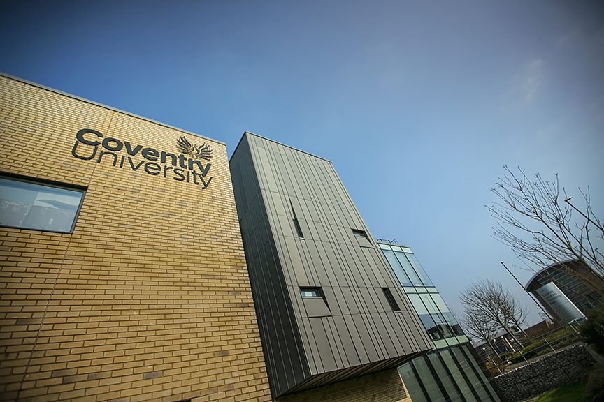
CMD Ltd, the specialist in power distribution solutions and workstation power and ergonomics, has provided under desk and on desk power modules for the refurbishment of three Coventry University research buildings. Located on Coventry University Technology Park, a business park designed to encourage collaboration between the university and knowledge-based businesses, the three buildings are being repurposed as office accommodation for university research teams. The refurbishment...

Read more
Coventry University

How to Choose an Impulse Voltage Generator in 2026?

Choosing an Impulse Voltage Generator in 2026 requires more than comparing maximum voltage ratings. The right system must match your test objects, waveform requirements, laboratory space, and verification procedures. A generator designed for lightning impulse testing may not suit switching impulse applications. That distinction matters.

Begin with the required impulse shape, such as the standard 1.2/50 μs waveform. Check voltage range, energy capacity, charging speed, and load behavior under actual test conditions. A larger rating is not automatically better. It can increase cost, floor-space demands, and safety complexity. Consider the test specimen carefully. A transformer bushing, cable termination, or power electronic module may respond differently to the same nominal impulse.

Practical experience also reveals details that brochures often simplify. Ask whether the control system records voltage, current, timing, and oscillation clearly. Confirm that measurement dividers, grounding systems, and calibration services support reliable results. Verify alignment with current IEC or equivalent laboratory standards, then request documented test data from the manufacturer. Specifications should be independently reviewed.

The choice is rarely obvious. One overlooked issue can delay commissioning. Some suppliers offer impressive peak voltage figures but provide limited support for routine maintenance or waveform correction. Others may deliver strong hardware with weak software documentation. That gap deserves attention. A responsible selection process compares technical evidence, operator training, service response, and total ownership cost. It should also include a realistic risk assessment before installation. In 2026, the best generator is not simply the most powerful model. It is the one that produces repeatable, traceable impulses for your specific testing work.

How to Choose an Impulse Voltage Generator in 2026?

Define the Test Objective: 1.2/50 μs Lightning or 8/20 μs Current Impulses

Choosing an impulse voltage generator starts with the test objective, not the advertised peak voltage. For insulation coordination, the target is usually a 1.2/50 μs lightning impulse. IEC 60060-1 defines this waveform with a 1.2 μs front time and a 50 μs time to half-value. The generator must therefore control wave shape, overshoot, polarity, and measurement accuracy. IEEE Std 4-2013 also emphasizes calibrated voltage measurement and repeatable impulse parameters. A 500 kV rating alone proves little.

The requirement changes for an 8/20 μs current impulse. This waveform reaches its crest in about 8 μs and falls to half value near 20 μs. IEC 62475 identifies it as a standard high-current test waveform for surge-protection evaluation. Select the generator by peak current, transferred charge, source impedance, and test-object inductance. A short, wide conductor can matter more than another impressive specification. In practical laboratory work, failed tests often come from poor grounding or unsuitable shunts, not insufficient generator power. Check the oscilloscope bandwidth and calibration records. Then verify the waveform under the actual load. That step is easy to skip. It should not be. Reports from the International Electrotechnical Commission and IEEE remain more reliable than simplified catalogue tables, although even those standards require engineering judgment for unusual equipment.

How to Choose an Impulse Voltage Generator in 2026? - Define the Test Objective: 1.2/50 μs Lightning or 8/20 μs Current Impulses

Test Objective Standard Impulse Primary Quantity Typical Test Application Key Waveform Parameters Generator Selection Criteria Measurement and Safety Priorities
Lightning impulse insulation test 1.2/50 μs
Standard switching and lightning impulse voltage waveform
High-voltage impulse Insulation coordination and dielectric withstand testing of electrical equipment, insulation systems, bushings, transformers, cables and other high-voltage components Front time: approximately 1.2 μs
Time to half-value: approximately 50 μs
Polarity: positive, negative or both, depending on the test plan
Select a voltage impulse generator with sufficient peak voltage, charging voltage, energy and test-object capacitance range. The output circuit should support waveform adjustment and low-inductance connections. Use a calibrated high-voltage divider and impulse recorder. Provide controlled earthing, adequate clearance, interlocks, discharge equipment and a defined approach boundary.
Surge protective device current test 8/20 μs
Standard current impulse waveform
High-current impulse Surge protective devices, varistors, gas discharge devices, semiconductor protection components, bonding conductors and lightning-current protection paths Front time: approximately 8 μs
Time to half-value: approximately 20 μs
Peak current and transferred charge depend on the selected test level
Select a current impulse generator based on peak current, open-circuit voltage, short-circuit current, load impedance, required repetition rate and the device’s expected energy absorption. Use a calibrated current shunt or suitable current transformer with adequate bandwidth. Keep the high-current loop short and rigid, and verify thermal, mechanical and arc-flash controls.
Combined voltage-current surge test Application-specific combination of voltage and current impulses Voltage and current simultaneously or sequentially Complete surge protection assemblies, coordinated protection systems and equipment exposed to both insulation stress and conducted surge current The voltage and current waveforms are influenced by the generator, source impedance, test object and connection layout. They should be verified at the test terminals. Consider a dedicated combination-wave system or coordinated voltage and current sources. Confirm peak voltage, peak current, source impedance, coupling method and energy delivered to the test object. Synchronize measurement channels and confirm insulation, grounding and trigger performance before applying full energy. Record both applied and residual waveforms where applicable.
Generator output capability Not defined by waveform alone Peak value, energy and repetition capability Any impulse test where the nominal waveform is correct but the generator may not deliver the required stress to the actual load The connected test object can change rise time, decay time, peak value and oscillation. Generator ratings should therefore be checked with the intended load, not only under open-circuit conditions. Compare peak voltage or current, stored energy, effective source impedance, capacitance or inductance range, charging time, trigger stability and maximum permissible repetition rate. Check the complete measurement chain, including sensors, dividers, cables, bandwidth, grounding and calibration uncertainty. Use acceptance limits defined by the applicable test standard.
Waveform verification 1.2/50 μs or 8/20 μs nominal shape Time-domain conformity Routine validation, type testing, laboratory commissioning and troubleshooting of impulse test systems Confirm front time, time to half-value, peak value, polarity, overshoot, oscillation and reproducibility. The permissible tolerances depend on the applicable standard and test configuration. Choose a generator with practical adjustment of resistors, inductors, capacitors or equivalent control elements so the required waveform can be obtained at the test object. Measure at the defined reference point using traceable instruments. Document the test circuit, load condition, waveform parameters, environmental conditions and any deviations.
Decision rule for 2026 selection Define the objective before selecting the generator Match source type to stress type Prevent purchasing a voltage impulse generator for a current impulse requirement, or a current source for an insulation withstand requirement A 1.2/50 μs test is principally a voltage insulation test; an 8/20 μs test is principally a current surge test. Their generators, sensors, connection layouts and safety controls are different. First specify the waveform and test object. Then calculate the required peak value, load range, energy, repetition rate, measurement bandwidth and future expansion needs. Require documented calibration, interlocked operation, emergency discharge, remote control where appropriate, guarded test areas and procedures consistent with the laboratory’s electrical safety program.

Match Generator Voltage to Equipment Ratings from 1 kV to 1,200 kV

How to Choose an Impulse Voltage Generator in 2026?

Match Generator Voltage to Equipment Ratings from 1 kV to 1,200 kV

Selecting an impulse voltage generator begins with the equipment’s insulation rating, not its operating voltage alone. A 1 kV device may require a carefully controlled impulse, while a 1,200 kV system demands greater clearance, energy, and measurement accuracy. The generator should reach the specified test level without operating continuously at its limit. A small margin helps, but excessive capacity can increase cost and laboratory risks.

Check the required waveform, polarity, front time, and tail time. Lightning impulse and switching impulse tests place different demands on the circuit. Equipment capacitance also affects the delivered waveform. A generator that looks suitable on paper may produce poor results with a large transformer bushing or long cable. This detail is easy to miss.

The voltage divider and recording system must match the generator range. At high voltage, stray capacitance, grounding layout, and room dimensions can change the measured peak. At lower levels, background noise may reduce accuracy. Choose calibrated measurement equipment with traceable records and documented uncertainty. Safety interlocks, discharge resistors, barriers, and remote operation deserve equal attention. More voltage is not automatically better. I would question any selection based only on the highest number. Testing conditions often reveal that the practical choice needs less capacity, better control, or a different generator configuration.

Select Energy and Capacitance Using IEC 60060-1 Test Requirements

Choosing an impulse voltage generator begins with the IEC 60060-1 test waveform, not the headline voltage. For lightning impulses, the standard specifies a nominal 1.2/50 μs wave. Its key tolerances are approximately ±30% for front time and ±20% for time to half-value. IEEE Std 4-2013 provides closely aligned measurement guidance. These figures directly influence generator capacitance, charging voltage, and wave-shaping resistance.

Use E = ½CV² to estimate stored energy. A generator charged to 1,000 kV with 20 nF stores about 10 kJ. That is only a starting point. The test object, divider, leads, and resistors also absorb energy. A practical design may require 20–30% additional capacitance, depending on leakage and waveform losses. My first estimate is often too optimistic. That shortcut can fail during full-voltage testing.

For switching impulses, IEC 60060-1 uses a much slower waveform, commonly 250/2,500 μs. Larger capacitance usually supports the longer duration, but it can reduce charging speed and increase physical size. Select the charging unit after calculating repetition rate, not before. Record the expected load capacitance and verify the waveform under actual connection conditions. A 5% change in load can alter the front time noticeably in a compact circuit. Review test records against IEC 60060-1:2010 and IEEE Std 4-2013. Standards specify acceptance limits, but they do not choose the generator for you.

Verify Waveform Accuracy Under IEC 60060-2 Measurement Standards

How to Choose an Impulse Voltage Generator in 2026?

Verify Waveform Accuracy Under IEC 60060-2 Measurement Standards

Selecting an impulse voltage generator in 2026 requires more than checking peak voltage. The measurement system must demonstrate waveform accuracy under IEC 60060-2 standards. Demand traceable calibration records. Confirm that the generator’s output range suits your test objects. A high voltage rating alone proves little. Experienced laboratories also examine repeatability, triggering stability, and safe energy discharge.

For lightning impulses, inspect front time, time to half-value, overshoot, and oscillation. Use calibrated voltage dividers and a measuring system with suitable bandwidth. Cable layout matters. Even a small ground loop can distort the recorded front. Compare several captured impulses, rather than one attractive trace. Keep raw data, calibration dates, environmental conditions, and uncertainty calculations. These records support audits and technical investigations.

During acceptance testing, measure at different voltage levels. Check whether the waveform remains compliant near both operating limits. A generator may appear stable at 50 percent output, then reveal ringing at full charge. That happened during one practical evaluation, and the first inspection missed it. Our process focused too heavily on peak value. A stronger review includes independent verification, repeated tests, and clear criteria for invalid measurements. Choose controls that expose drift, not equipment that only produces impressive numbers.

How to Choose an Impulse Voltage Generator in 2026? - Verify Waveform Accuracy Under IEC 60060-2 Measurement Standards

The chart compares the nominal IEC lightning impulse waveform of 1.2/50 µs with an illustrative measured trace. When selecting an impulse voltage generator, verify peak voltage, front time, time to half-value, calibration traceability, and the measurement-system uncertainty evaluation required by IEC 60060-2.

Reference dimensions: nominal front time 1.2 µs and nominal time to half-value 50 µs. The measured trace shown is a screening example rather than a compliance certificate; final verification should use a calibrated divider, validated recording system, and documented uncertainty results.

Compare Safety, Charging Speed, Automation, and Calibration Features

How to Choose an Impulse Voltage Generator in 2026?

Safety should lead the comparison. Choose a generator with a grounded enclosure, door interlocks, emergency discharge, and visible warning indicators. IEC 60060-1:2020 emphasizes controlled conditions for high-voltage impulse testing. In practice, a safer design reduces rushed adjustments and accidental exposure. Check the discharge time, not only the warning lamp. Faster charging improves productivity, but excessive speed can increase stress on capacitors and switching parts. Ask for charging curves at your required voltage, load, and repetition rate.

Automation matters when tests must be repeated accurately. Look for programmable voltage, polarity, wave shape, trigger delay, and automatic fault logging. A clear software audit trail helps technicians find missed settings. It is not perfect. Some systems automate too much and hide useful diagnostic details. Prefer manual override with permission controls. Calibration should support traceability to national standards. NIST Technical Note 1297 explains that an expanded uncertainty with coverage factor k=2 commonly represents about 95% coverage. ISO/IEC 17025:2017 also stresses competent calibration and valid measurement results.

Tips: Compare real test data, not brochure peaks. Request ten-shot repeatability records. Review calibration certificates carefully. Verify rise time with your actual divider and oscilloscope. A generator may meet its specification only under ideal conditions. That detail is easy to miss.