

News

Miro: A New Standard in Responsible Innovation

Miro: A New Standard in Responsible Innovation The Miro monitor arm is setting new benchmarks in sustainability. It offers a high-performance solution without compromising on environmental responsibility. Designed with careful material selection, local sourcing, and longevity in mind, Miro’s responsible approach to design and unique manoeuvrability set it apart from the competition. Sustainable Choices Miro is crafted from energy-efficient materials with a lower carbon impact....

Read more
HSE Advisor

Role Purpose Support in the development, implementation and maintenance of the company’s Health, Safety & Environmental policies, processes, operational procedures, and standards.  Ensuring best practice and championing a continually improving HSE culture within the business. Key Responsibilities Liaise with and provide support to all areas of the business to eliminate, mitigate or reduce identified HSE exposures. Partner with the production management team and team leaders,...

Read more
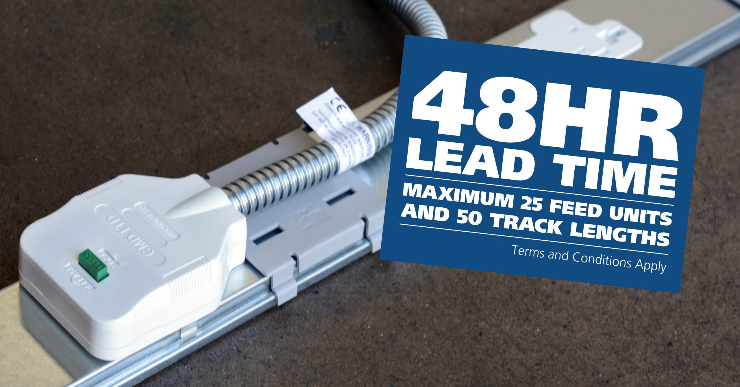
CMD Ltd LAUNCHES 48-HOUR TURNAROUND ON BETATRAK® RAPID ORDERING SERVICE

CMD Ltd, the specialist in power distribution systems, workstation power and monitor arms, has launched a rapid ordering service for its Betatrak® underfloor powertrack distribution systems and accessories, with a commitment to delivering within 48-hours of an approved purchase order*. The service enables customers to order up to 50 lengths of Standard or Clean Earth (C/E) low noise Betatrak, along with up to 25 feed...

Read more
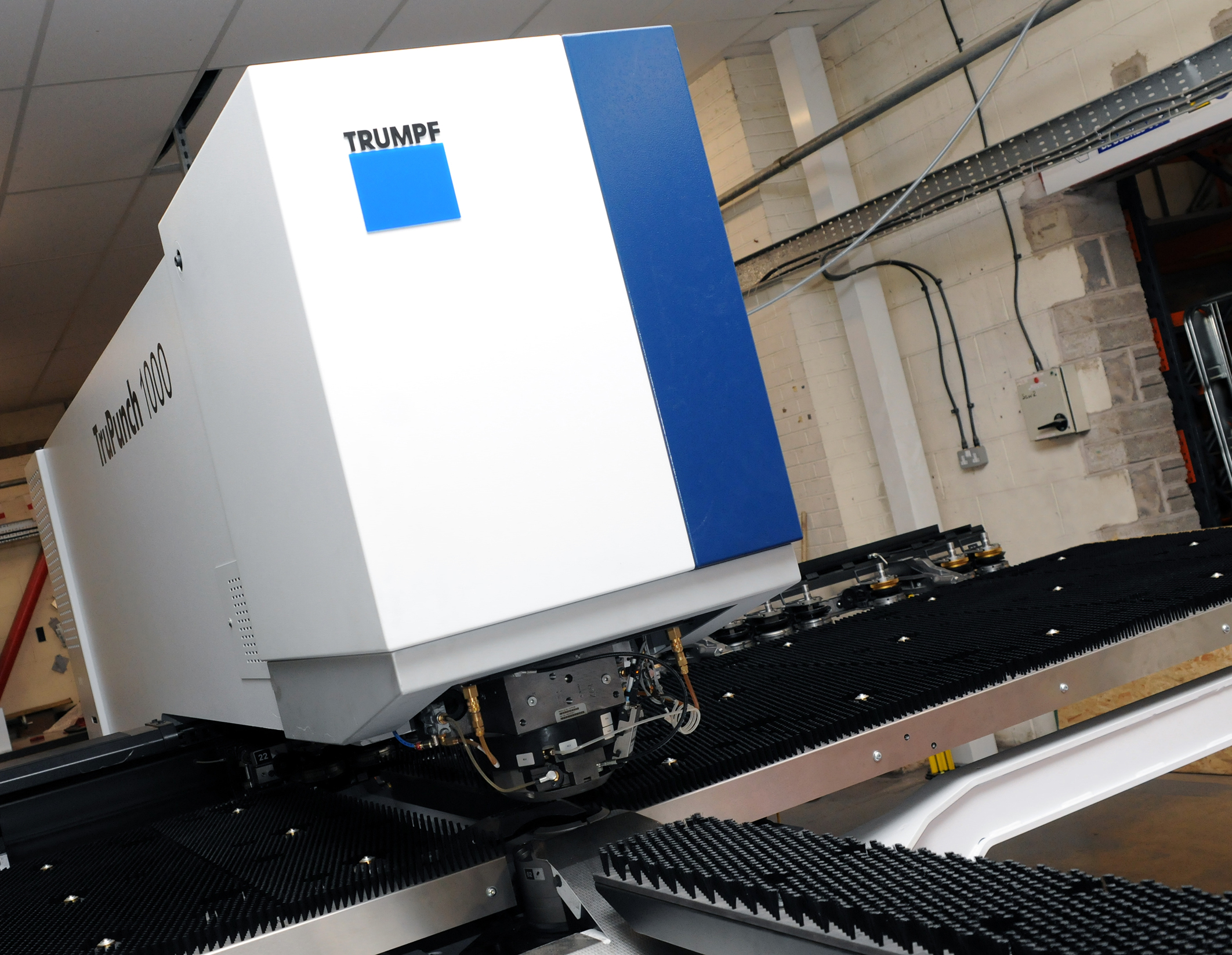
CMD INVESTS £1/4 MILLION IN NEW MACHINE AS PART OF FACTORY UPGRADE

We have invested in a new £1/4m TRUMPF CNC metal punch as part of an asset renewal strategy for our UK manufacturing capability. The new machine will be used in the production of a wide variety of our power distribution systems and workstation power products at our Rotherham factory. Suitable for handling sheet metal between 0.9mm and 3.0mm thick, the new machine will replace one...

Read more
CMD CATALOGUE PROVIDES TECHNICAL POWER DISTRIBUTION GUIDE

CMD Ltd has released a new catalogue, providing an easy to follow technical guide to our power distribution systems and plug and play desk modules. Detailing CMD’s full range of UK-manufactured power distribution systems and plug and play desk modules, the catalogue will be a helpful source of information to M&E engineers and contractors alike to understand how our power distribution systems connect together and...

Read more
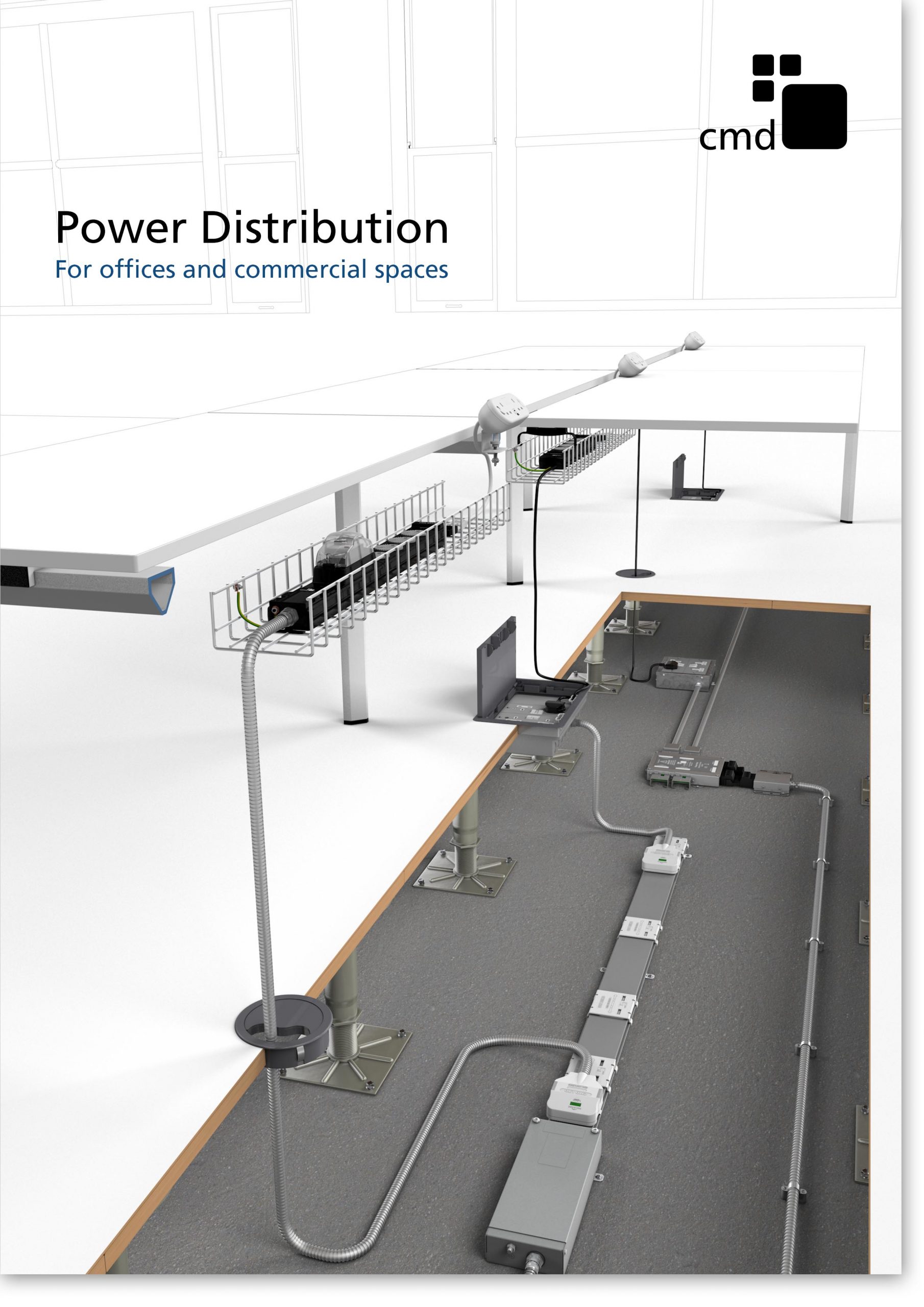
Power Distribution Catalogue
CMD Ltd PLAYS ESSENTIAL ROLE IN ELECTRICAL FIT OUT AT LONDON’S PRESTIGIOUS OFFICE DEVELOPMENT

CMD Ltd, specialist in workplace connectivity and ergonomic solutions, has provided a flexible and high-quality power distribution network for The Ray, a prestigious office development in London’s Farringdon. Well-known for being the former site of The Guardian newspaper, The Ray now stands as an 83,000ft² office development characterised by a modernised warehouse aesthetic, with level two now occupied by a global social media company. The...

Read more

The Ray
CMD plugs in to european opportunity with Schuko Capsule unit launch

CMD Ltd, the specialist in power and connectivity solutions for commercial environments, has launched a Schuko version of its popular fixed format Capsule workstation power module for export to mainland Europe and beyond. A popular on desk power module comprising two sockets and dual USB (type A and C) chargers, CMD’s Capsule unit is already widely specified in the UK as an off-the-shelf workstation power...

Read more
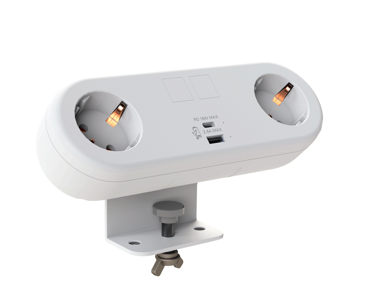
CMD White Schuko Capsule Desk Power Module
CMD LTD EXTENDS MONITOR ARM RANGE WITH THE LAUNCH OF REACH PLUS

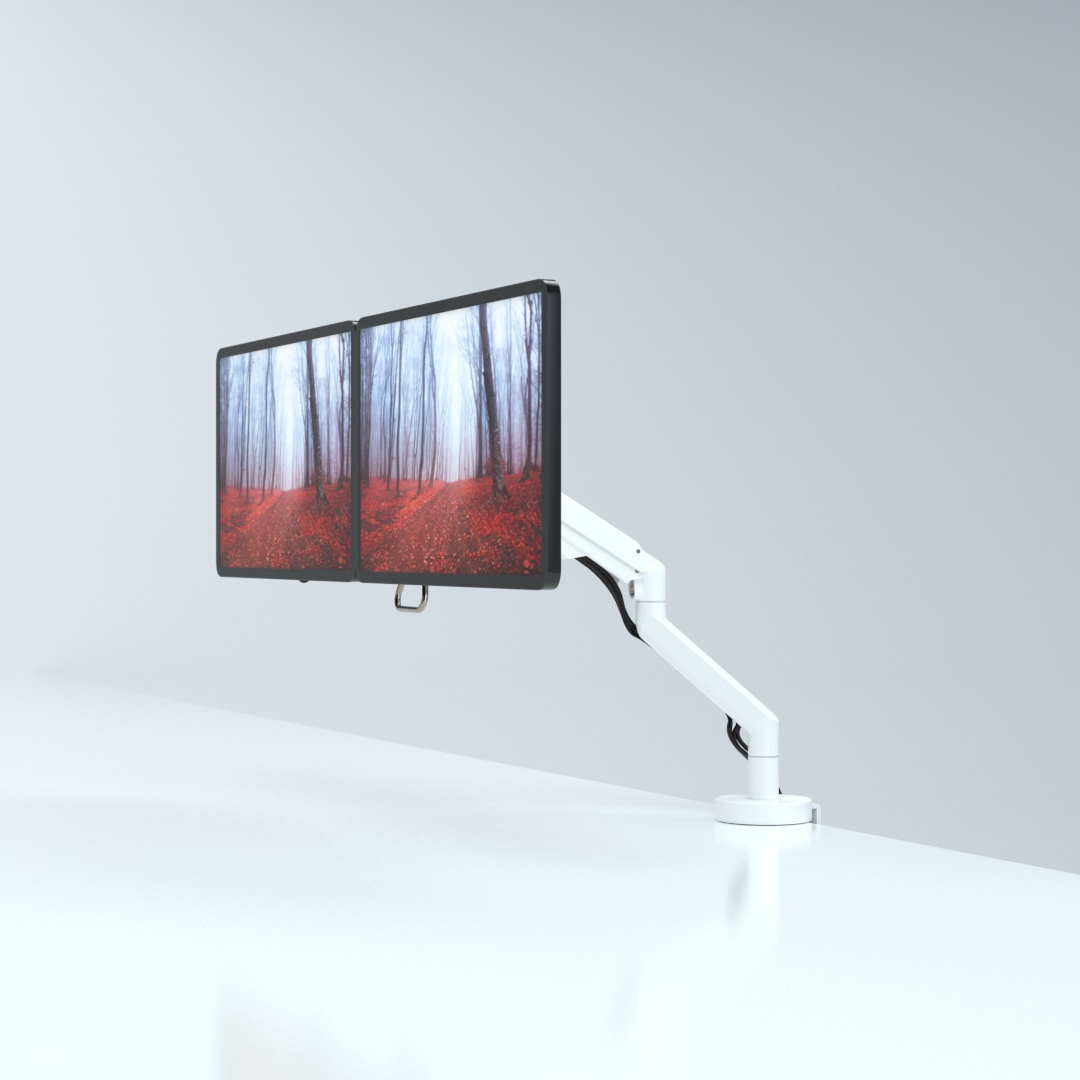
CMD Ltd, the specialist in ergonomic and connectivity solutions for commercial interiors, has completed its Reach monitor arm range with the launch of the Reach Plus. Available in single or dual screen options, the Reach Plus has been designed to provide an ideal solution for both single and dual screen workstation configurations, or can be used with next generation of large format curved screens. Suitable...

Read more
CMD Ltd DEMONSTRATES THE ART OF POWER DISTRIBUTION AT THE UNIVERSITY OF WARWICK

CMD Ltd, the specialist in workplace connectivity and ergonomic solutions, has provided Betatrak busbar power distribution and a range of electrical accessories for two major capital investment projects at the University of Warwick. Designed by Fielden Clegg Bradley Studios, the £33 million Faculty of Arts building is a showpiece development comprising four interconnected structures set around a central atrium, which will enable inter-disciplinary collaboration across...

Read more

University of Warwick
CMD BRINGS HARMONY TO COVENTRY UNIVERSITY RESEARCH FACILITIES

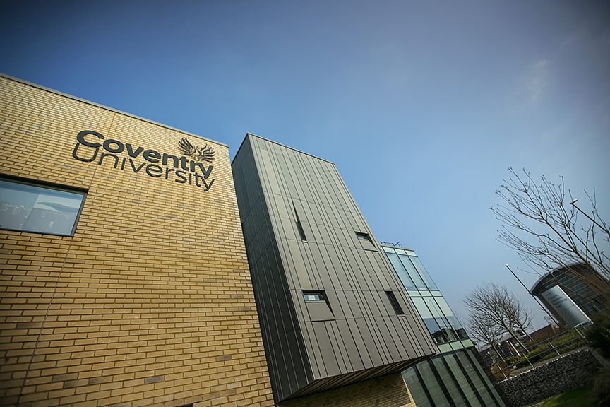
CMD Ltd, the specialist in power distribution solutions and workstation power and ergonomics, has provided under desk and on desk power modules for the refurbishment of three Coventry University research buildings. Located on Coventry University Technology Park, a business park designed to encourage collaboration between the university and knowledge-based businesses, the three buildings are being repurposed as office accommodation for university research teams. The refurbishment...

Read more
Coventry University

How to Choose a Single Phase 10V Rectifier in 2026?

Choosing the right Single Phase 10v Rectifier in 2026 requires more than matching a voltage label. The term “10V” may describe the expected DC output, an operating point, or a nominal rating. Confirm this detail before comparing products. A rectifier designed for 10V DC can behave differently under load, especially when the input supply fluctuates.

Start with the electrical conditions. Check the AC input range, maximum forward current, surge current, reverse voltage, and expected ripple. A bridge rectifier may be compact, but its diode drops can reduce the available output voltage. That loss matters in low-voltage circuits. Measure the voltage after the transformer, rectifier, and filter capacitor. Small differences become visible on a bench meter.

Thermal performance deserves equal attention. Inspect the package, mounting method, airflow, and rated temperature. A component rated for 10 amps may need substantial cooling to operate safely. Review the manufacturer’s datasheet, test conditions, warranty terms, and quality certifications. Independent distributor records can also reveal inconsistent stock or unclear specifications. Do not trust attractive listings alone.

Practical testing helps.

Use a controlled load and record temperature over time. Check startup behavior, ripple, and voltage recovery after a sudden load change. An oscilloscope provides better evidence than a multimeter alone. Still, no selection method is perfect. Real installations contain wiring resistance, enclosure heat, and aging capacitors. A careful buyer should leave reasonable safety margin and document every assumption. That discipline makes the final choice more reliable, even when the available specifications are incomplete.

How to Choose a Single Phase 10V Rectifier in 2026?

What Is a Single-Phase 10V Rectifier?

A single-phase 10V rectifier converts alternating current from one AC phase into low-voltage direct current. A diode bridge is commonly used for this task. Four diodes guide both halves of the AC waveform toward one output polarity. The result is not perfectly smooth DC. It contains ripple, which usually requires a capacitor, regulator, or downstream filter.

The “10V” rating needs careful interpretation. It may describe nominal DC output, transformer secondary voltage, or maximum reverse voltage. These meanings are not interchangeable. After bridge losses, a 10V AC input can produce roughly 12.7V peak before load and ripple effects. Under real load, heat and transformer resistance reduce that value. I have seen designs fail because this simple distinction was ignored.

Choose current capacity with headroom. A circuit drawing 1A should not normally use a 1A rectifier continuously. Temperature, enclosure airflow, capacitor charging surges, and repetitive peak current all matter. The IEC 61000-3-2 standard addresses harmonic current limits for applicable equipment, while IEC 62368-1 supports safety evaluation of power supplies. These standards do not select the component for you. They expose weak assumptions. A 2024 analysis by Grand View Research valued the global power electronics market at over USD 30 billion, reflecting demand for efficient conversion, but market growth does not guarantee a suitable 10V design. Check isolation, ripple voltage, thermal rise, and measured output under the worst load. A bench test is still necessary.

How to Match Voltage, Current, and Rectifier Type

Choosing a single-phase 10V rectifier starts with identifying what the 10V actually describes. It may mean a 10V AC input, a 10V DC output, or a component’s voltage rating. These are not interchangeable. A 10V AC source reaches about 14.1V peak before diode losses. After bridge rectification and filtering, the no-load DC voltage may approach 12.7V. Measure the transformer under load, not only on its label.

Current matching requires more than reading the equipment’s normal consumption. Select a rectifier whose average forward current exceeds the expected load, preferably with practical thermal margin. Check surge current when capacitors charge or motors start. Heat matters. At higher current, forward voltage creates noticeable power loss. For example, a 1.1V drop at 3A produces about 3.3W of heat. That small package may become surprisingly hot.

Rectifier type also changes performance. A full-wave bridge uses both AC half-cycles and usually gives smoother output with smaller filtering requirements. A half-wave design may be acceptable for very light loads, but its ripple and transformer utilization are poorer. Verify peak inverse voltage, or PIV, against the circuit’s highest possible reverse voltage. I once treated a “10V” source as fixed and selected too little voltage margin. It worked on the bench, then failed during switching. Leave room for line variation, temperature, and imperfect assumptions. Review the datasheet’s derating curves and test the assembled circuit at its warmest expected condition.

Which Diode Configuration Best Fits Your Application?

Choosing a single-phase 10V rectifier begins with the diode configuration, not the package label. Confirm whether 10V means RMS AC or a regulated DC input. A 10V RMS source reaches about 14.1V peak before diode losses. That difference matters.

A bridge rectifier usually fits compact power supplies because it uses both half-cycles and needs no center-tapped transformer. Two diodes conduct simultaneously, however. At low voltage, their combined forward drop can waste a noticeable share of the output. A center-tapped full-wave circuit uses one conducting diode, but transformer utilization is poorer and the required peak inverse voltage is higher. Half-wave rectification is simple, though ripple and transformer stress often make it unsuitable for continuous loads.

The best choice depends on load current, ripple limits, temperature, and surge conditions. Schottky diodes can reduce forward loss, but leakage rises with temperature. Standard silicon diodes may offer greater ruggedness and lower cost. Check the datasheet at the actual current, not at the headline rating. Measure the transformer waveform.

The WSTS Spring 2025 forecast valued global semiconductor sales at about 697 billion dollars for 2025, showing continued demand for efficient power devices. Yet market growth does not replace engineering checks. IEC 60747-2 provides useful diode rating guidance, while IEC 62368-1 supports equipment-level safety evaluation. I would still verify reverse voltage, inrush current, thermal rise, and capacitor ripple experimentally. My first selection may be wrong. That is worth discovering early.

How to Choose a Single Phase 10V Rectifier in 2026? - Which Diode Configuration Best Fits Your Application?
Diode Configuration Required Diodes Input Arrangement Ripple Frequency Typical DC Output from 10 Vrms AC* Approximate Diode Voltage Loss Advantages Limitations Best-Fit Application
Half-Wave Rectifier 1 Single AC winding or source 50 Hz with 50 Hz input
60 Hz with 60 Hz input
Approximately 4.3 V DC without a smoothing capacitor About 0.7–1.1 V for a standard silicon diode at moderate current Lowest component count; simple circuit; low cost; easy to troubleshoot High ripple; poor transformer utilization; higher peak and RMS current in the diode; less suitable for efficient power conversion Very low-power sensing, simple bias supplies, indicator circuits, and non-critical loads
Full-Wave Bridge Rectifier 4 Single AC winding; no center tap required 100 Hz with 50 Hz input
120 Hz with 60 Hz input
Approximately 7.6 V DC without a smoothing capacitor About 1.4–2.2 V total because two diodes conduct in each half-cycle Two forward voltage drops reduce low-voltage efficiency; heat dissipation must be checked at higher current
Full-Wave Center-Tapped Rectifier 2 Transformer with a center-tapped secondary; each half-winding conducts alternately 100 Hz with 50 Hz input
120 Hz with 60 Hz input
Approximately 3.6 V DC when the complete secondary is 10 Vrms end-to-end and each half is 5 Vrms About 0.7–1.1 V because only one diode conducts at a time Lower conduction loss than a bridge; useful when a center-tapped transformer already exists Requires a special transformer; only half of the winding is used during each half-cycle; higher diode reverse-voltage requirement Low-loss circuits using an existing center-tapped transformer or designs requiring a reduced diode drop
Voltage-Doubler Rectifier 2 Single AC winding with two capacitors and two diodes Usually 100 Hz with 50 Hz input
120 Hz with 60 Hz input
Up to approximately 26–27 V DC peak under light load from 10 Vrms AC; practical loaded voltage is lower Approximately 1.4–2.2 V total during the charging path Can produce a higher DC voltage without a higher transformer secondary voltage; useful where current demand is limited Higher output impedance; greater voltage sag and ripple under load; capacitor voltage ratings must be sufficient Low-current high-voltage bias supplies, compact auxiliary rails, and circuits needing more than the input peak voltage
Schottky-Diode Bridge 4 Single AC winding; bridge arrangement 100 Hz with 50 Hz input
120 Hz with 60 Hz input
Approximately 8.0–8.8 V DC without a smoothing capacitor, depending on current About 0.4–0.8 V per conducting diode; approximately 0.8–1.6 V per current path Higher reverse leakage; typically lower reverse-voltage margin than silicon rectifiers; leakage increases with temperature Low-voltage, high-efficiency supplies where every volt of headroom matters
Synchronous MOSFET Rectifier 2–4 MOSFETs plus control circuitry Controlled replacement for diode conduction paths Normally 100 Hz or 120 Hz for a single-phase full-wave design Can approach the rectified waveform peak more closely than diode circuits; output depends on MOSFET resistance and control timing Conduction loss is approximately I²R; may be lower than diode loss at high current Higher cost and complexity; requires gate-drive timing, startup protection, and careful control of reverse current High-current 10 V systems, battery-powered equipment, and designs where efficiency is more important than circuit simplicity
*Reference conditions: 10 Vrms single-phase AC input, 50 or 60 Hz, resistive load, no voltage-regulator drop, and no smoothing-capacitor peak charging. Actual output depends on load current, transformer regulation, diode temperature, diode forward current, capacitor size, and allowable ripple. For most standard 10 V AC applications, a four-diode full-wave bridge is the most balanced choice; Schottky diodes are preferable when low forward loss is critical.

How to Evaluate Heat Dissipation and Electrical Safety

How to Choose a Single Phase 10V Rectifier in 2026?

Heat dissipation should be checked before current capacity. A rectifier may deliver 10V, yet still produce significant heat internally. Measure forward voltage drop and expected load current. Their product determines power loss. For example, a 0.9V drop at 3A creates 2.7W of heat. That heat needs a clear path through the case, mounting surface, and surrounding air.

Use the datasheet’s thermal resistance, not guesswork. A metal plate, thermal pad, or finned heatsink can reduce junction temperature. Keep airflow openings away from dust and cable bundles. Check the enclosure temperature after one hour at the highest expected ambient temperature. A thermal camera helps, but a basic contact probe can expose hot spots. My first estimate once seemed safe, but a tightly enclosed prototype ran much hotter than expected.

Electrical safety also requires careful margin. Select a reverse-voltage rating well above the circuit’s peak transient voltage. Add suitable fusing, secure terminals, and strain relief for every cable. Maintain adequate creepage and clearance distances around live parts. Insulate exposed conductors and prevent accidental contact during adjustment. Confirm polarity before energizing the circuit. A small warning label is useful, but physical barriers are more reliable. Do not treat a 10V output as harmless; stored energy and fault currents can still cause burns or equipment damage. Document test conditions, because results can change with airflow, load, and mounting pressure.

How to Choose a Single-Phase 10V Rectifier in 2026?

Evaluating heat dissipation and electrical safety

Engineering basis: The chart assumes a 10 V AC RMS input, a full-wave bridge with two conducting diodes, a typical forward voltage of 1.0 V per silicon diode and 0.55 V per low-forward-voltage diode. Estimated junction temperature uses a 25 °C ambient temperature and a 10 °C/W thermal resistance.

Electrical safety check: A 10 V AC RMS input reaches approximately 14.1 V peak. Selecting a rectifier with a repetitive peak reverse voltage rating of at least 40 V provides practical voltage margin for normal transients. Confirm the actual surge rating, creepage, clearance, insulation system and fuse coordination from the component datasheet and end-product standard.

How to Install, Test, and Maintain a 10V Rectifier in 2026

When choosing a single-phase 10V rectifier, confirm the required DC current before installation. A 10V label describes output voltage, not total system capacity. Check the transformer’s secondary voltage, the expected load, and the rectifier’s surge rating. Select a bridge unit with comfortable current headroom. Leave space for airflow. A design can look correct and still overheat.

Switch off all power before wiring. Connect the two AC terminals to the transformer secondary, then connect the positive and negative DC terminals to the load. Use correctly sized wires, secure terminals firmly, and place suitable protection near the supply. Keep exposed conductors covered.

My early installations sometimes used cables that were too long, causing unnecessary voltage drop. Measure twice.

Test the rectifier with a calibrated multimeter before connecting sensitive equipment. Check polarity, then measure DC voltage without a load. The reading may exceed 10V, especially with a lightly loaded transformer. Add the intended load and measure again.

Watch for excessive ripple, buzzing, hot terminals, or a burning smell.

During maintenance, isolate power, clean dust, inspect corrosion, and retighten loose connections. Record voltage and temperature readings during each service visit. This record helps reveal gradual failure. I still recheck assumptions when readings seem normal, because a brief test can miss heat buildup or intermittent contact.