

News

Miro: A New Standard in Responsible Innovation

Miro: A New Standard in Responsible Innovation The Miro monitor arm is setting new benchmarks in sustainability. It offers a high-performance solution without compromising on environmental responsibility. Designed with careful material selection, local sourcing, and longevity in mind, Miro’s responsible approach to design and unique manoeuvrability set it apart from the competition. Sustainable Choices Miro is crafted from energy-efficient materials with a lower carbon impact....

Read more
HSE Advisor

Role Purpose Support in the development, implementation and maintenance of the company’s Health, Safety & Environmental policies, processes, operational procedures, and standards.  Ensuring best practice and championing a continually improving HSE culture within the business. Key Responsibilities Liaise with and provide support to all areas of the business to eliminate, mitigate or reduce identified HSE exposures. Partner with the production management team and team leaders,...

Read more
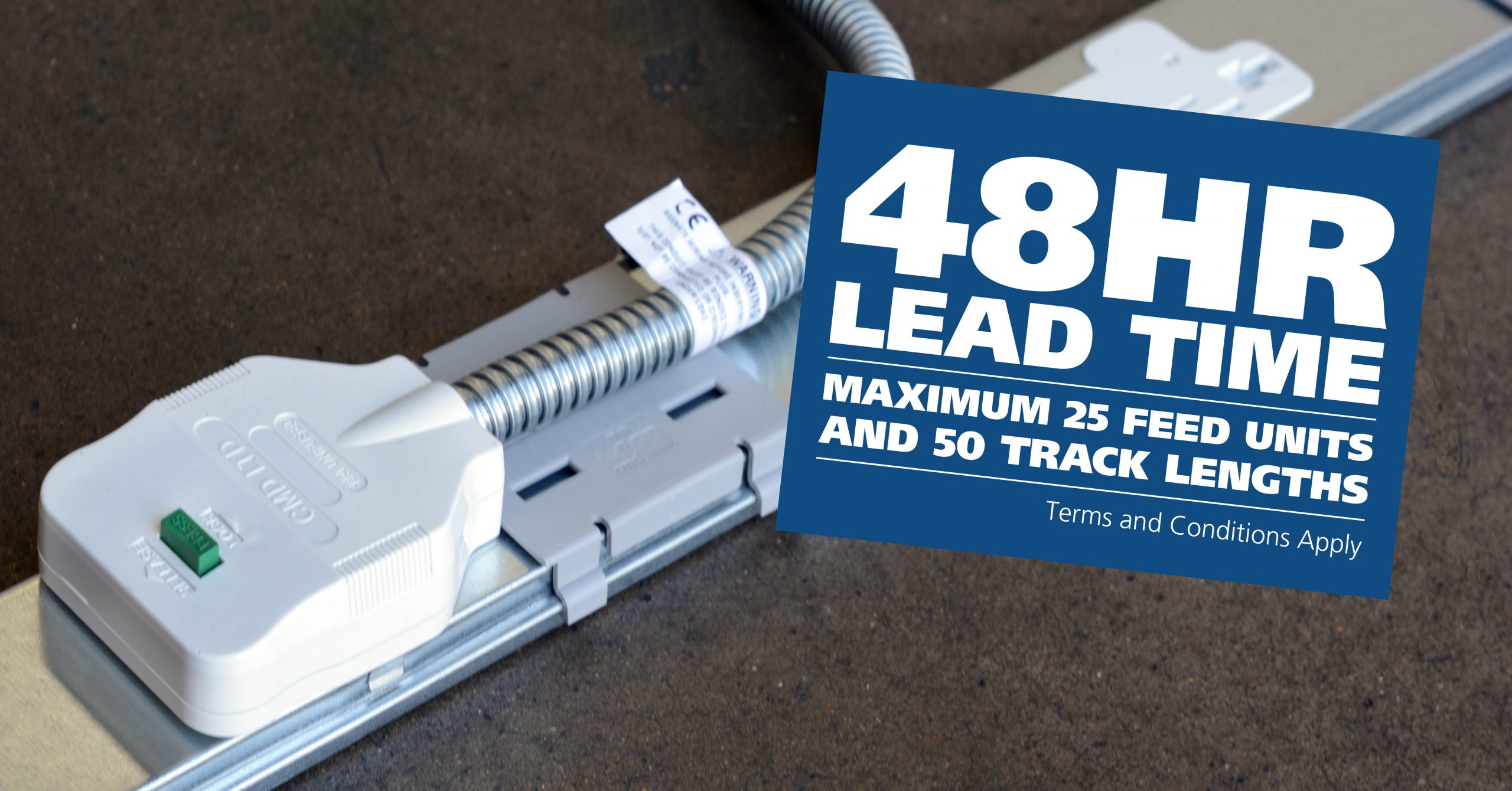
CMD Ltd LAUNCHES 48-HOUR TURNAROUND ON BETATRAK® RAPID ORDERING SERVICE

CMD Ltd, the specialist in power distribution systems, workstation power and monitor arms, has launched a rapid ordering service for its Betatrak® underfloor powertrack distribution systems and accessories, with a commitment to delivering within 48-hours of an approved purchase order*. The service enables customers to order up to 50 lengths of Standard or Clean Earth (C/E) low noise Betatrak, along with up to 25 feed...

Read more
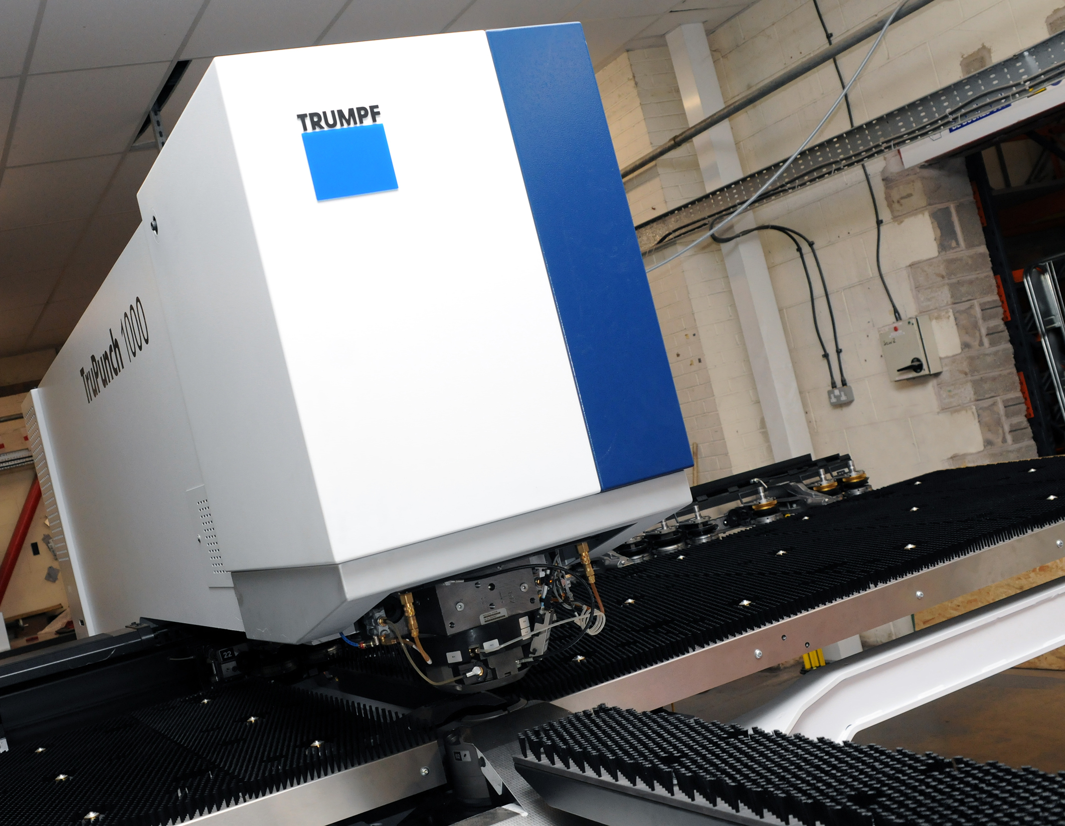
CMD INVESTS £1/4 MILLION IN NEW MACHINE AS PART OF FACTORY UPGRADE

We have invested in a new £1/4m TRUMPF CNC metal punch as part of an asset renewal strategy for our UK manufacturing capability. The new machine will be used in the production of a wide variety of our power distribution systems and workstation power products at our Rotherham factory. Suitable for handling sheet metal between 0.9mm and 3.0mm thick, the new machine will replace one...

Read more
CMD CATALOGUE PROVIDES TECHNICAL POWER DISTRIBUTION GUIDE

CMD Ltd has released a new catalogue, providing an easy to follow technical guide to our power distribution systems and plug and play desk modules. Detailing CMD’s full range of UK-manufactured power distribution systems and plug and play desk modules, the catalogue will be a helpful source of information to M&E engineers and contractors alike to understand how our power distribution systems connect together and...

Read more
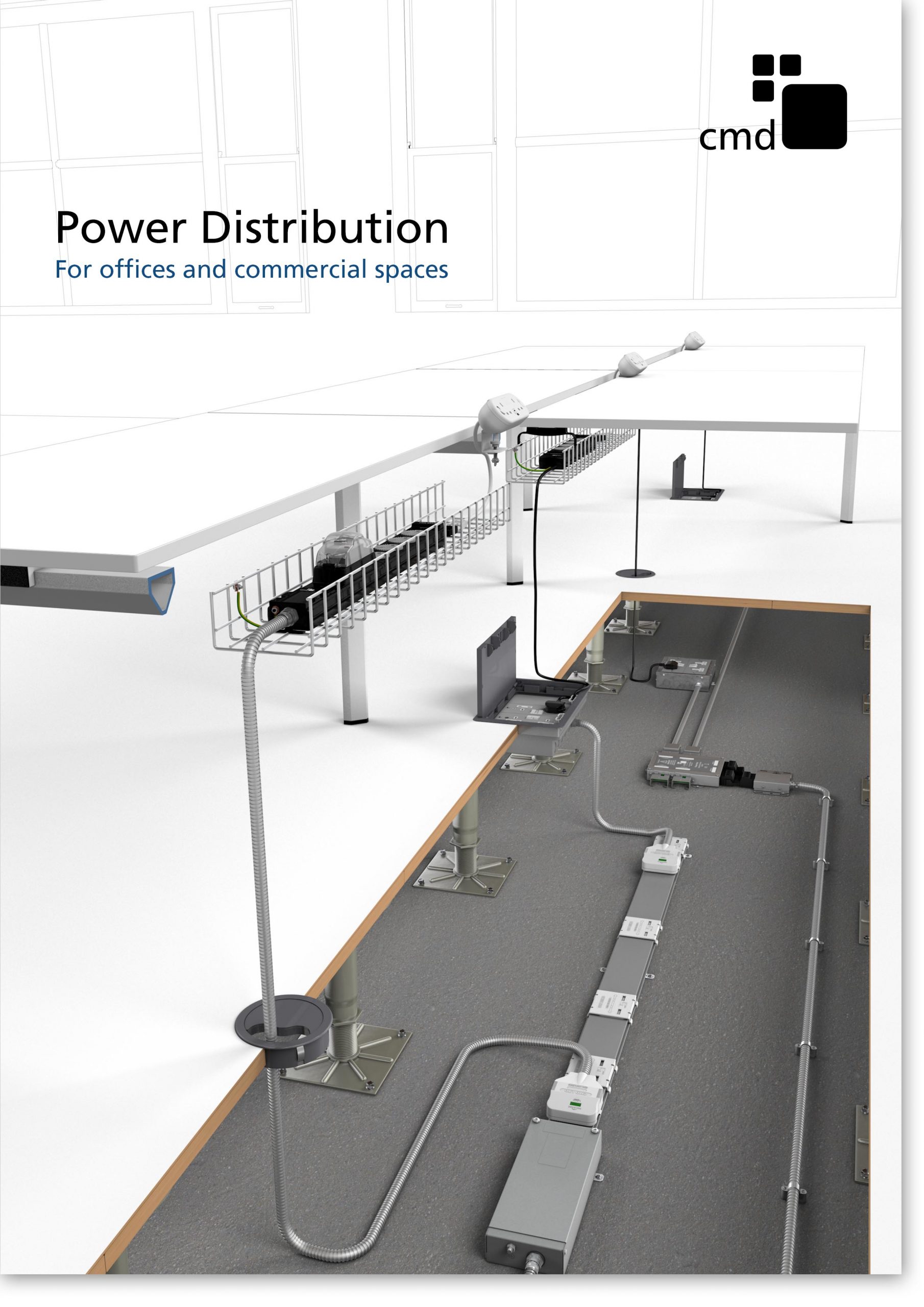
Power Distribution Catalogue
CMD Ltd PLAYS ESSENTIAL ROLE IN ELECTRICAL FIT OUT AT LONDON’S PRESTIGIOUS OFFICE DEVELOPMENT

CMD Ltd, specialist in workplace connectivity and ergonomic solutions, has provided a flexible and high-quality power distribution network for The Ray, a prestigious office development in London’s Farringdon. Well-known for being the former site of The Guardian newspaper, The Ray now stands as an 83,000ft² office development characterised by a modernised warehouse aesthetic, with level two now occupied by a global social media company. The...

Read more

The Ray
CMD plugs in to european opportunity with Schuko Capsule unit launch

CMD Ltd, the specialist in power and connectivity solutions for commercial environments, has launched a Schuko version of its popular fixed format Capsule workstation power module for export to mainland Europe and beyond. A popular on desk power module comprising two sockets and dual USB (type A and C) chargers, CMD’s Capsule unit is already widely specified in the UK as an off-the-shelf workstation power...

Read more
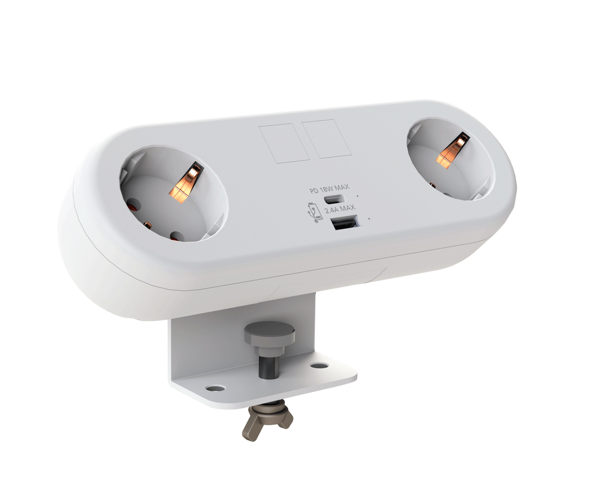
CMD White Schuko Capsule Desk Power Module
CMD LTD EXTENDS MONITOR ARM RANGE WITH THE LAUNCH OF REACH PLUS

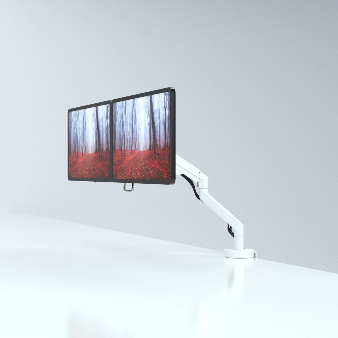
CMD Ltd, the specialist in ergonomic and connectivity solutions for commercial interiors, has completed its Reach monitor arm range with the launch of the Reach Plus. Available in single or dual screen options, the Reach Plus has been designed to provide an ideal solution for both single and dual screen workstation configurations, or can be used with next generation of large format curved screens. Suitable...

Read more
CMD Ltd DEMONSTRATES THE ART OF POWER DISTRIBUTION AT THE UNIVERSITY OF WARWICK

CMD Ltd, the specialist in workplace connectivity and ergonomic solutions, has provided Betatrak busbar power distribution and a range of electrical accessories for two major capital investment projects at the University of Warwick. Designed by Fielden Clegg Bradley Studios, the £33 million Faculty of Arts building is a showpiece development comprising four interconnected structures set around a central atrium, which will enable inter-disciplinary collaboration across...

Read more

University of Warwick
CMD BRINGS HARMONY TO COVENTRY UNIVERSITY RESEARCH FACILITIES

CMD Ltd, the specialist in power distribution solutions and workstation power and ergonomics, has provided under desk and on desk power modules for the refurbishment of three Coventry University research buildings. Located on Coventry University Technology Park, a business park designed to encourage collaboration between the university and knowledge-based businesses, the three buildings are being repurposed as office accommodation for university research teams. The refurbishment...

Read more


Coventry University

Why Choose Flexible Busbar for Electrical Projects?

Why Choose Flexible Busbar for Electrical Projects? The question becomes practical when power systems face tighter spaces, faster installation schedules, and rising load density. The International Energy Agency estimated that data centers consumed about 415 TWh of electricity worldwide in 2024. It also projects demand could reach roughly 945 TWh by 2030. These figures highlight a growing need for compact, adaptable distribution systems.

Flexible Busbar can support that need with a movable, low-profile connection between transformers, switchboards, and equipment. Its bendable construction helps installers route conductors around columns, cable trays, and crowded plant rooms. In real projects, that can reduce sharp bends and simplify alignment during equipment changes. It may also shorten installation time compared with many individual cables, although results depend on design and site conditions. Small details matter. Correct torque matters.

Industry guidance should remain central. IEC 61439 provides important requirements for low-voltage switchgear and controlgear assemblies, including verification, temperature rise, and short-circuit performance. Designers should confirm the complete system’s ratings rather than rely on product appearance alone. The Uptime Institute’s data-center research also shows that resilience, maintainability, and capacity planning strongly influence electrical infrastructure decisions. Flexible Busbar is not automatically the best answer. Poor routing, inadequate support, or unclear fault calculations can undermine its benefits. That is where experienced engineers add value: reviewing load profiles, ambient temperatures, protection coordination, and future expansion before selecting a system. The choice deserves evidence, not enthusiasm.

Why Choose Flexible Busbar for Electrical Projects?

What Is a Flexible Busbar?

A flexible busbar is a compact electrical conductor designed to carry substantial current while allowing controlled movement.

It usually contains layered copper or aluminum strips, often covered with insulation. The layers can slide slightly during bending, unlike a solid, rigid busbar.

It is not simply a thick cable.

A cable uses stranded conductors inside a flexible sheath, while a flexible busbar keeps a broad, flat profile. This shape can reduce connection distance between switchgear, transformers, and distribution panels. It also helps manage heat because the conductor offers a large surface area.

In practical installation work, technicians can form the busbar around tight corners and align it with uneven terminal positions. Fewer joints may be needed. That can simplify inspection.

Good design still matters.

The conductor size must match the expected current, short-circuit conditions, temperature, and enclosure space. Bending should follow the manufacturer’s stated radius and direction. Excessive folding can damage insulation or weaken the laminated structure. It may look easy to shape.

Flexible busbars can also reduce vibration stress between connected equipment.

However, they are not a universal replacement for cables or rigid busbars. Engineers should verify insulation ratings, clearance, creepage distance, terminal compatibility, and applicable electrical standards.

Installation records should include torque values and visual checks. A small alignment error can create pressure at the terminal, and that problem may remain hidden until heating occurs.

How Flexible Busbars Work in Electrical Systems

Flexible busbars work as compact current paths between switchgear, transformers, distribution panels, and battery systems. They usually contain thin copper or aluminum layers, joined and covered with insulation. Current flows through the metal layers, while the insulation separates phases and protects nearby components.

Their flexible structure allows controlled bending during installation. It also absorbs vibration, thermal expansion, and small alignment differences. This can simplify crowded electrical layouts and reduce connection stress. However, flexibility does not mean unlimited movement. A sharp bend, excessive twisting, or poor support can damage the conductor. Field conditions often expose this weakness. A neat installation can still have an incorrect bend radius.

Tips: Check the rated current, insulation class, short-circuit capacity, and operating temperature. Follow the specified bend radius and support spacing. Clean contact surfaces before connection, then tighten terminals to the approved torque. Keep required clearances around energized parts. Qualified personnel should verify the design and test continuity before energizing the system. Small details matter.

Key Advantages of Flexible Busbars

Flexible busbars offer practical advantages in crowded electrical projects. Their laminated copper construction bends around tight corners and reduces the need for multiple cable lugs. During panel installation, technicians can align connections more easily, especially near breakers, transformers, and distribution blocks. Fewer joints may also reduce potential heating points.

The main advantage is installation flexibility. A busbar can follow a short, direct route instead of taking a wide cable loop. This saves cabinet space and can improve airflow around energized components. Its broad contact surface supports efficient current transfer when correctly sized and installed. Insulated versions also help control accidental contact risks during routine maintenance.

Installation quality still matters. I have seen flexible busbars twisted too sharply, leaving stress near the terminals. That mistake can weaken insulation or loosen hardware over time. Respect the manufacturer’s bend radius, torque values, temperature rating, and short-circuit requirements. Check the actual load, not only the normal operating current. Heat inside a sealed enclosure may change the result. Flexible does not mean unlimited.

They also perform well where vibration occurs, such as industrial machinery or transport-related equipment. Movement is absorbed more effectively than with rigid connections. However, every project has different clearances, fault levels, and maintenance needs. A flexible busbar may simplify one connection while complicating another. Careful inspection remains essential.

Applications in Modern Electrical Projects

Why Choose Flexible Busbar for Electrical Projects?

Flexible busbars are changing how engineers route power in modern electrical projects. Their compact structure fits tight cabinets, switchboards, and modular distribution systems. Unlike rigid copper links, they can bend around short offsets and absorb minor alignment differences. This flexibility reduces drilling, cutting, and on-site adjustment. That matters.

In data centers, flexible busbars connect power distribution units to cabinets where equipment layouts change frequently. In solar and battery storage installations, they handle connections between converters, inverters, and battery enclosures. Manufacturing lines also use them near motors, control panels, and movable machine sections. In commercial buildings, they support riser connections and compact switchgear assemblies. Proper insulation and clearance remain essential. A flexible conductor is not automatically a safe conductor.

From field experience, reliable results depend on more than ampacity. Engineers should verify short-circuit withstand, bend radius, temperature rise, vibration exposure, and terminal compatibility. Installation teams need clean contact surfaces and controlled tightening torque. I have seen small alignment errors create avoidable stress at terminals. Flexible busbar can solve that problem, but poor routing can create another one. Designers should allow inspection access and future expansion space. Testing should include insulation resistance and thermal checks under realistic load conditions. Standards and project specifications must guide every selection, since local conditions vary. A thinner assembly may appear efficient, yet its service life can be disappointing.

How to Select the Right Flexible Busbar

Why Choose Flexible Busbar for Electrical Projects?

How to Select the Right Flexible Busbar

Selecting a flexible busbar starts with the electrical load, not the available shelf space. Check the continuous current, system voltage, short-circuit withstand, and expected temperature. A busbar rated for normal operation may still fail under heat or fault conditions. Space matters. Measure the enclosure carefully, including door movement and nearby cable bends.

Review the conductor material and cross-sectional area with a qualified electrical engineer. Copper usually offers strong conductivity, while aluminum can reduce weight in suitable applications. Confirm the insulation type, temperature rating, flame performance, and resistance to moisture or chemicals. The minimum bending radius must match the installation route. Tight bends can damage insulation or weaken connection points.

Connection quality deserves close attention. Verify terminal width, bolt spacing, plating compatibility, and required torque. A polished drawing can hide a practical problem. During one installation review, a flexible link matched the current rating but touched a sharp enclosure edge. The design needed a protective sleeve and a wider bend. Do not guess. Inspect samples, follow applicable electrical standards, and request test records for current capacity, insulation resistance, and short-circuit performance. Leave room for thermal expansion and future maintenance. A reliable choice is the one that still performs safely after installation, inspection, and repeated movement.