7 Tips for Choosing an Object Space Telecentric Lens
Choosing an object space telecentric len is not simply a matter of selecting the highest magnification. The lens must match the camera sensor, working distance, field of view, aperture, and measurement tolerance. A small mismatch can create large errors. For example, a metal pin may appear correctly sized at the center, yet change noticeably when it moves several millimeters from the designed working distance. That is where telecentric design becomes valuable.
Dr. John E. Greivenkamp, an optical engineering educator, has explained, “Telecentric imaging keeps measured size from changing with object distance.” This principle guides reliable dimensional inspection. An object space telecentric len reduces perspective distortion because its chief rays remain nearly parallel in object space. The result is a more stable image of edges, holes, molded parts, and machined surfaces. However, telecentricity does not solve every problem. Illumination, sensor resolution, vibration, and lens alignment still matter. No lens choice is perfect.
The seven tips in this guide examine practical selection decisions. They cover telecentricity, magnification, working distance, depth of field, sensor compatibility, lighting, and installation space. Check the actual part, not only the catalog drawing. A glossy black component may need coaxial lighting. A deep cavity may require more depth of field than expected. These details are easy to overlook.
There is also a practical compromise. Higher optical performance often means a larger, heavier, and more expensive lens. A careful evaluation should compare measurement repeatability, not just purchase price. Test representative parts before final approval. Small experiments can expose assumptions that specifications hide.
Understanding Object Space Telecentric Lens Design and Applications
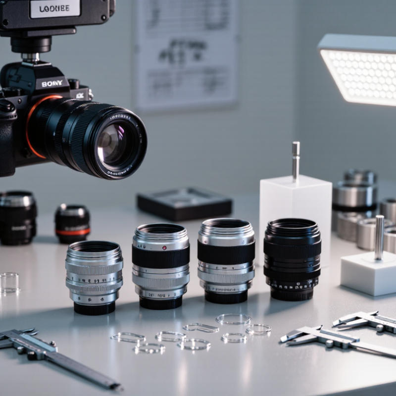
Choosing an object space telecentric lens starts with understanding its optical design. Its chief rays remain nearly parallel in object space, so magnification changes less when an object moves in depth. This helps measure diameter, height, and edge position accurately. Check the required field of view, sensor size, working distance, and object depth before selecting one. A lens that fits the sensor may still fail when its working distance is too short.
The aperture stop is central to telecentric performance. A carefully positioned stop supports parallel light paths and reduces perspective error. However, telecentricity is never perfectly unlimited. Ask for the specified telecentric angle, distortion value, and usable depth range. Keep these details in the inspection record. Small errors matter. For shiny metal parts, controlled backlighting can create a clean silhouette. For textured surfaces, diffuse illumination often reveals more reliable features. The lens cannot fix poor lighting.
Applications include dimensional inspection, semiconductor alignment, medical component measurement, and automated assembly. In practice, I would test the lens with calibrated targets at several depths. Measure the same feature repeatedly. Then compare results near the image center and corners. This exposes distortion, focus limits, and mounting sensitivity. One overlooked issue is vibration. A stable lens cannot compensate for an unstable fixture. I also prefer leaving some resolution margin, although this can increase system cost. That trade-off deserves honest review. Select the lens as part of the complete imaging system, not as an isolated component.
Defining Magnification, Working Distance, and Field of View
Choosing an object space telecentric lens starts with the image, not the lens catalog. Define required magnification by comparing the object’s real size with its image size. A 10 mm feature that must appear as 2 mm needs 0.2x magnification. Keep measurement units consistent. Small errors here can distort every later decision. Start with the part. Confirm the sensor size and pixel pitch, because resolution depends on the complete imaging chain.
Working distance is the space from the lens reference surface to the target plane. Leave room for lighting, clamps, and part movement. In production, a few extra millimeters can prevent costly interference. Do not estimate this distance by eye. Measure it twice. Then check the lens’s specified tolerance. A telecentric lens maintains consistent scale across depth, but it cannot correct poor fixturing. I have seen stable optics produce unstable measurements when parts tilted slightly.
Field of view should cover the entire part while preserving useful pixels on critical edges. Calculate it from sensor dimensions and magnification, then add a practical margin. Too little margin causes missed features; too much reduces detail. Check distortion, depth of field, illumination compatibility, and aperture settings with real samples. A perfect calculation can still fail under dust, vibration, or reflective surfaces. Test several parts, record repeatability, and question results that look unusually clean. This habit is often overlooked.
7 Tips for Choosing an Object Space Telecentric Lens - Defining Magnification, Working Distance, and Field of View
Generic selection reference for machine-vision applications | Tip | Selection Dimension | Typical Requirement | Example Value | Why It Matters | Practical Check |
| 1 | Magnification | Match the object size to the active sensor area. | 0.50× | A 0.50× lens forms an image half the object’s linear size on the sensor. | Use: Magnification = sensor dimension ÷ object dimension. |
| 2 | Field of View | Cover the complete inspection area with sufficient margin. | 24 mm × 18 mm | A field of view that is too small crops the part; excessive unused area reduces sampling efficiency. | For a 12 mm × 9 mm sensor at 0.50×: object-space FOV ≈ 24 mm × 18 mm. |
| 3 | Working Distance | Provide enough clearance for lighting, tooling, and part handling. | 110 mm | Working distance is measured from the lens reference surface to the object plane and affects system integration. | Allow additional space for protective windows, coaxial lighting, and mechanical tolerances. |
| 4 | Telecentricity | Measure edges or dimensions with minimal perspective error. | Object-space angle ≤ 0.10° | Chief rays remain nearly parallel in object space, helping maintain consistent apparent size across depth changes. | Confirm the specified telecentric angle or telecentricity error at the required magnification and field of view. |
| 5 | Depth of Field | Keep the entire measurement feature within acceptable focus. | ±1.0 mm | Higher magnification and larger numerical aperture generally improve resolution but can reduce usable depth of field. | Evaluate depth of field using the smallest feature and the maximum expected part-height variation. |
| 6 | Resolution and Pixel Sampling | Resolve the smallest defect with adequate pixels. | 4.8 µm/pixel | Object-space sampling is calculated by dividing sensor pixel size by magnification. | For a 2.4 µm pixel and 0.50× magnification: sampling = 2.4 ÷ 0.50 = 4.8 µm/object pixel. |
| 7 | Sensor and Mount Compatibility | Ensure the lens image circle and interface match the camera. | 2/3-inch sensor; C-mount | A lens designed for a smaller image circle can cause corner shading or vignetting on a larger sensor. | Check image-circle diameter, mount thread, flange distance, filter space, and camera sensor format. |
| Reference Calculation | Formula | Worked Example |
| Magnification | Sensor size ÷ object size | 12 mm sensor width ÷ 24 mm object width = 0.50× |
| Object-Space Field of View | Sensor dimension ÷ magnification | 12 mm ÷ 0.50 = 24 mm object-space width |
| Object-Space Pixel Sampling | Pixel size ÷ magnification | 2.4 µm ÷ 0.50 = 4.8 µm/pixel |
Matching Lens Specifications to Camera and Lighting Systems
7 Tips for Choosing an Object Space Telecentric Lens
Matching Lens Specifications to Camera and Lighting Systems
Tip 1: Start with the camera sensor, not the lens catalog. Match the lens image circle to the sensor size, then check pixel size and resolution. A large sensor cannot rescue a lens with weak edge performance. In inspection work, I have seen sharp centers hide blurred corners. That mistake wastes more time than expected.
Tip 2: Define the required field of view and working distance together. Calculate magnification from the object width and sensor width. Then confirm the lens supports that magnification at your available space. A telecentric lens may deliver excellent dimensional accuracy, yet become impractical near moving equipment. Leave room for cables, guards, and cleaning access.
Tip 3: Match aperture and lighting as a complete system. A small aperture can improve depth of field, but it also reduces image brightness. Use stable backlighting for silhouettes and controlled coaxial lighting for flat reflective surfaces. Diffuse lighting often reveals edges more reliably than intense light. This is easy to underestimate.
Tip 4: Check telecentricity, distortion, and depth of field in the actual setup. Published values may depend on specific test conditions. Measure a calibrated target at several object distances. Record edge position changes and repeatability. My early tests were too optimistic because the sample part was perfectly clean. Real parts were not. Consider vibration, surface variation, and exposure timing before approving the lens.
Checking Compatibility, Installation, and Long-Term Performance
7 Tips for Choosing an Object Space Telecentric Lens
Checking compatibility prevents expensive surprises. Match the lens to the sensor size, mount, magnification, and required working distance. Confirm the object field covers the entire part, including its edges. A lens can fit mechanically yet fail optically. Check twice. Review the wavelength range if your system uses colored lighting or infrared inspection. Also compare the aperture with your depth-of-field target. Higher magnification does not automatically produce better measurements.
Installation requires more than tightening a connector. Use a rigid mount and keep the lens axis square to the inspection surface. Even slight tilt can affect edge readings and create uneven focus. Center the illumination carefully, especially with backlighting. Set focus at the real working distance, not on a convenient test object. Leave enough clearance for cables, moving stages, and cleaning access. I once treated alignment as a quick adjustment. It was not.
Long-term performance depends on conditions around the lens. Check vibration, dust, humidity, and temperature changes before final selection. Lock adjustable parts after calibration, but avoid excessive force. Record the working distance, lighting settings, and reference measurements. Inspect images regularly for contrast loss, distortion, or unexpected shadows. Recalibration may be needed after relocation or strong thermal changes. A small compromise during installation can become a large measurement error later. Keep maintenance practical. Perfect plans sometimes fail on the factory floor.
7 Tips for Choosing an Object Space Telecentric Lens
The chart compares magnification stability when the object moves away from the nominal working distance. It uses a first-order thin-lens calculation with a 50 mm focal length and a nominal object distance of 1000 mm. A conventional lens changes magnification with object distance, while an ideal object-space telecentric lens maintains nearly constant magnification within its specified telecentric range.
When selecting a lens, verify sensor coverage and image-circle compatibility, working distance, telecentricity, mounting clearance, illumination access, calibration requirements, and long-term stability against temperature and mechanical vibration. Actual performance should always be confirmed using the lens specification and application test results.